Power unit and image forming apparatus provided with same mounted thereto

Inactive Publication Date: 2005-02-03
CANON KK
View PDF3 Cites 6 Cited by
  • Summary
  • Abstract
  • Description
  • Claims
  • Application Information

AI Technical Summary

Benefits of technology

[0013] It is another object of the present invention to provide an image forming apparatus with which the cost is reduced with the high operativity upon the mounting of the power unit.

Problems solved by technology

Despite the fact that it is intended to reduce the cost imparted to the user not requiring the option apparatus, the option voltage source apparatus is such as to cover all of the option apparatuses, and therefore, is expensive.
Therefore, when the option voltage source is mounted to the main assembly of the apparatus, a connector to which the option apparatus is connected has to be installed, with the result of time consuming operations.
This leads to cost increase of the main assembly of the apparatus, and therefore, the advantage of the option voltage source apparatus intended to reduce the cost is not provided enough.

Method used


Image

  • Power unit and image forming apparatus provided with same mounted thereto
  • Power unit and image forming apparatus provided with same mounted thereto
  • Power unit and image forming apparatus provided with same mounted thereto

Examples


Embodiment Construction

:

[0027] Referring to FIG. 3, the description will first be made as to a general arrangement of the main assembly of the image forming apparatus.

[0028] An original is placed on an original glass 201, and a copy key is depressed, in response to which the original exposure device 202 moves in the direction indicated by arrow A while illuminating the original to scan the whole surface of the original. The light reflected by the original in the original exposure device 202, is folded by second and third mirror 203 v and is image on a CCD204 by a lens. The original read by the CCD204 is converted to an electric signal in the image processor, and is supplied to a laser scanner 100. Then, image light corresponding to the image information from the laser scanner 100 is scanned by an image writing optical system and is image on the photosensitive drum 101 to form an electrostatic latent image. The electrostatic latent image is developed by a developing device 102.

[0029] On the other hand, r...


PUM


Abstract

An electric power unit for an option apparatus selectively mountable to an image forming apparatus, wherein the power unit is mounted to the image forming apparatus with mounting of the option apparatus, includes an electric power generating portion for generating electric power; and a connector for connection with the option apparatus to supply electric power from the electric power generating portion to the option apparatus.

Description

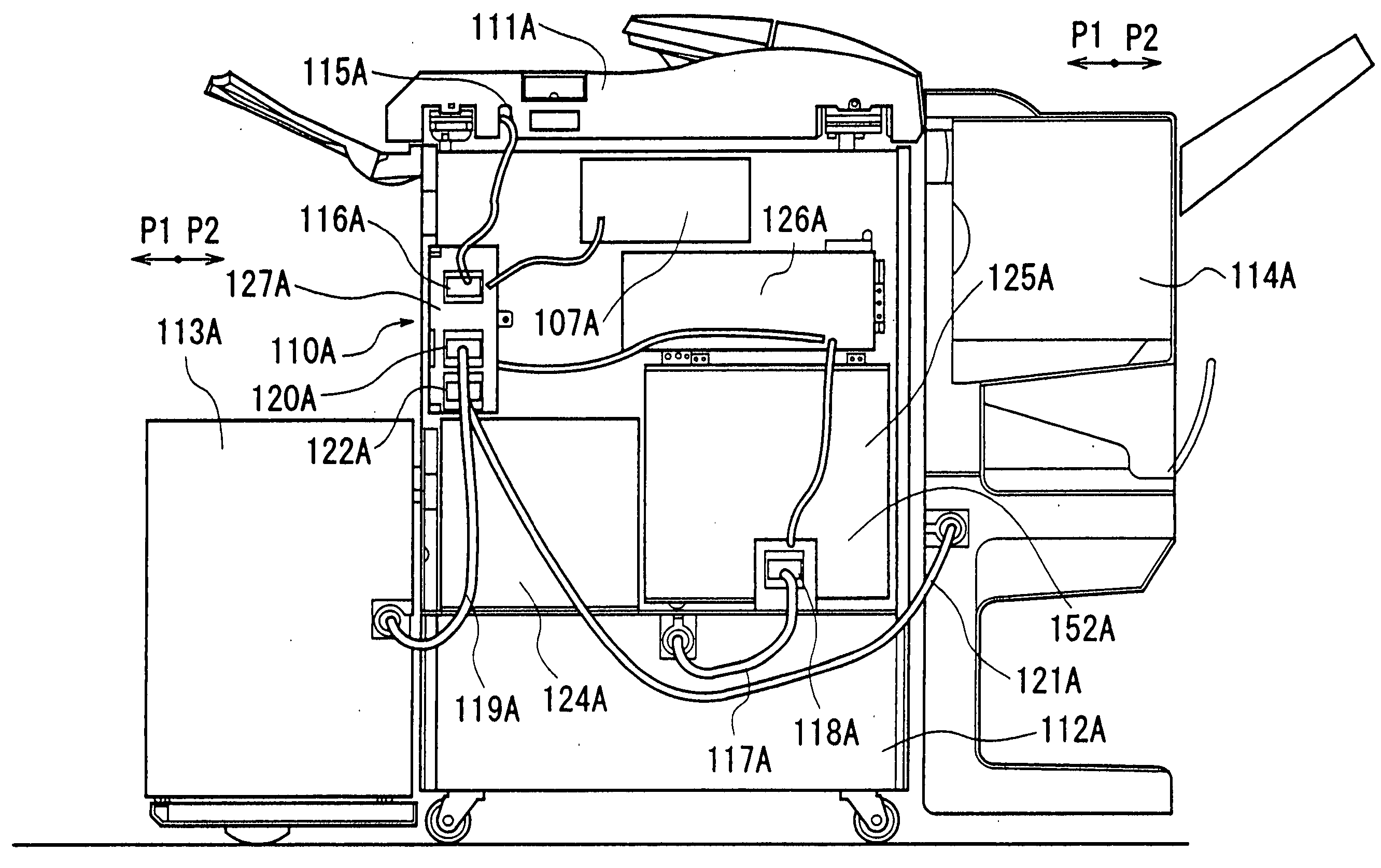
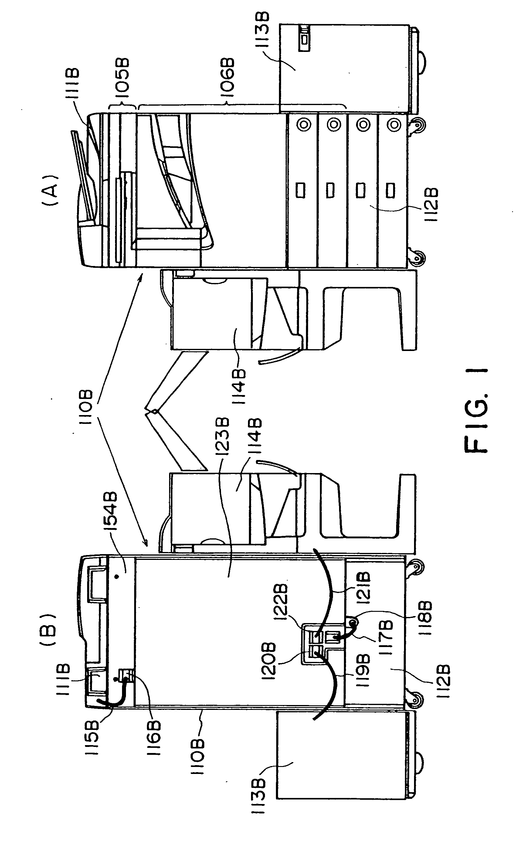
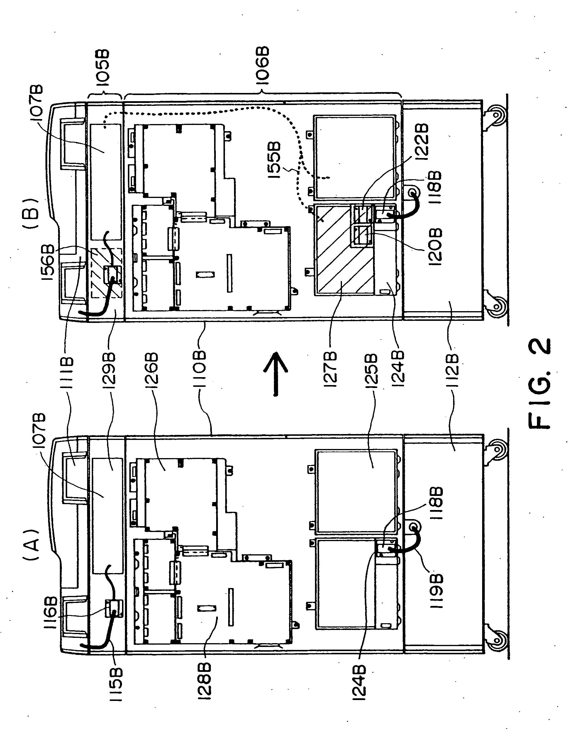
FIELD OF THE INVENTION AND RELATED ART [0001] The present invention relates to a power unit and an image forming apparatus to which the power unit is mounted. The power unit is usable with an image forming apparatus using an electrophotographic type, electrostatic recording type or the like process. The power unit is optionally installed in the image forming apparatus such as a copying machine, printer or the like when the user desires. [0002] Referring to FIGS. 9 and 10, a conventional example will be described. [0003] In this conventional example, the main assembly 110A comprises an original reading station (reader apparatus) 105A and an image formation station (printer) 106A. [0004] The copying image formation will be briefly described. Image information is obtained by scanning an original using the reader apparatus 105A. A photosensitive member is uniformly charged by charging means, and the surface of the photosensitive member is exposed to the image information by exposure mea...

Claims


Application Information

Patent Timeline
IPC IPC(8): B41J29/00G03G15/00H04N1/00
CPCG03G15/80
Inventor KITOZAKI, YUKIHIRO
Owner CANON KK
Why Eureka
Try Eureka