
Syringe assembly having disabling mechanism

Active Publication Date: 2005-02-03
BECTON DICKINSON & CO
View PDF59 Cites 29 Cited by
  • Summary
  • Abstract
  • Description
  • Claims
  • Application Information

AI Technical Summary

Benefits of technology

[0007] An operable syringe assembly having a passive disabling structure includes a barrel having a cylindrical sidewall with an inside surface defining a chamber for retaining fluid, an open proximal end and a distal end including a distal wall having a passageway therethrough in fluid communication with the chamber. An elongate hollow plunger rod having a proximal end, an open distal end, and an interior surface is provided. A stopper has a circular-shaped sealing element having a peripheral surface forming a seal with the inside surface of the barrel and a boss member projecting proximally from the sealing element. A locking element interacts between the stopper and the plunger rod. The locking element includes a central body portion having at least one cantilevered leg extending distally outwardly from the body portion wherein the leg includes a sharp free end directed outwardly for engaging the inside surface of the barrel. The locking element is movably connected to the boss of the stopper and movably connected to the plunger rod interior surface. Structure for indexing the locking element distally in the plunger rod during proximal motion of the plunger rod to draw fluid into the chamber and for indexing the locking element distally on the boss of the stopper during distally-directed motion of the plunger rod for delivering fluid from the chamber through the passageway and means for engaging the locking element with the inside surface of the barrel sidewall for preventing reuse of the syringe assembly is provided.
[0008] Structure for engaging the locking element with the inside surface of the barrel sidewall may include an opening in the distal end of the plunger rod to shorten the axial length of the interior surface area of the opening for allowing the sharp free end to project outwardly past the plunger rod and onto the inside surface of the barrel.

Problems solved by technology

Although many of these devices work quite well, they do require the specific intent of the user followed by the actual act to destroy or render the syringe inoperable.
These devices are not effective with a user having the specific intent to re-use the hypodermic syringe.
The automatic function is much harder to provide because the means for rendering the syringe inoperable must not prevent its filling or use under normal conditions.

Method used


Image

  • Syringe assembly having disabling mechanism
  • Syringe assembly having disabling mechanism
  • Syringe assembly having disabling mechanism

Examples


Embodiment Construction

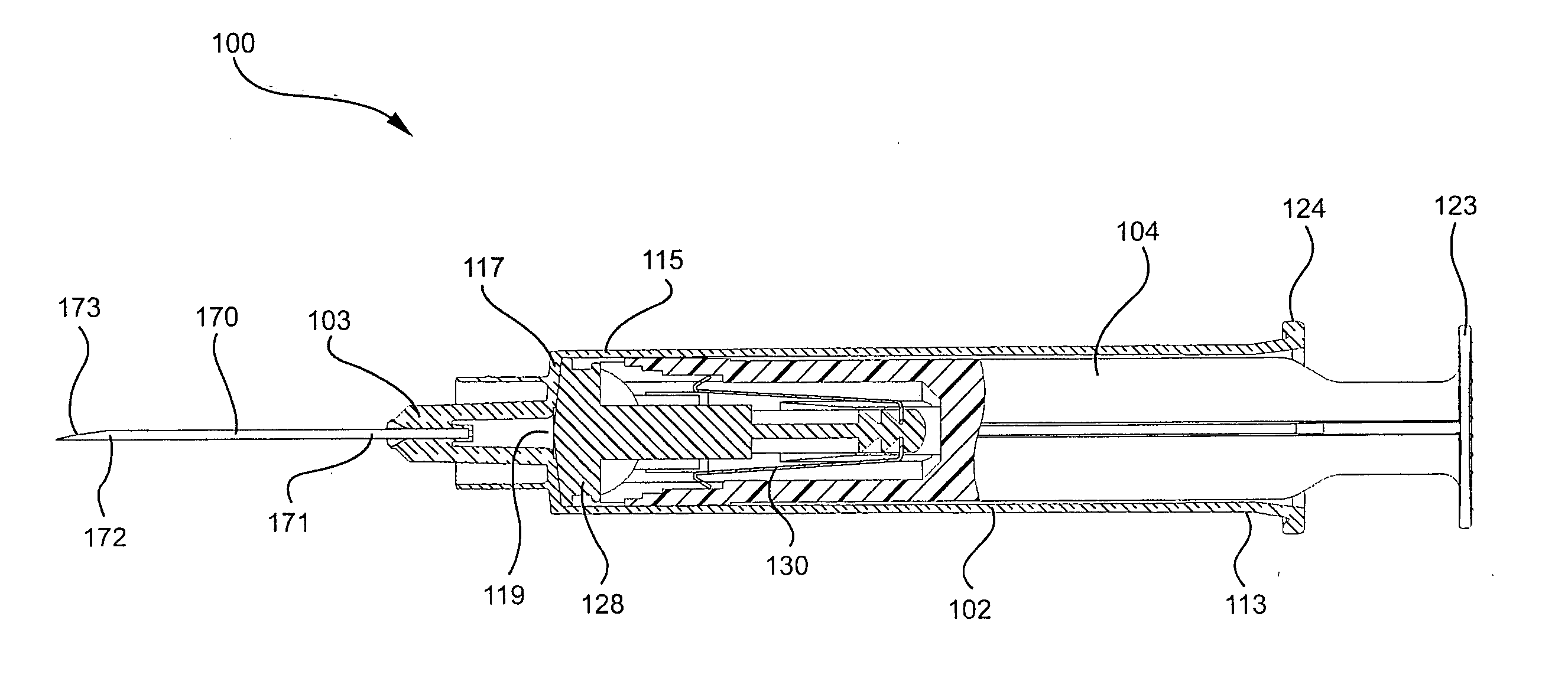
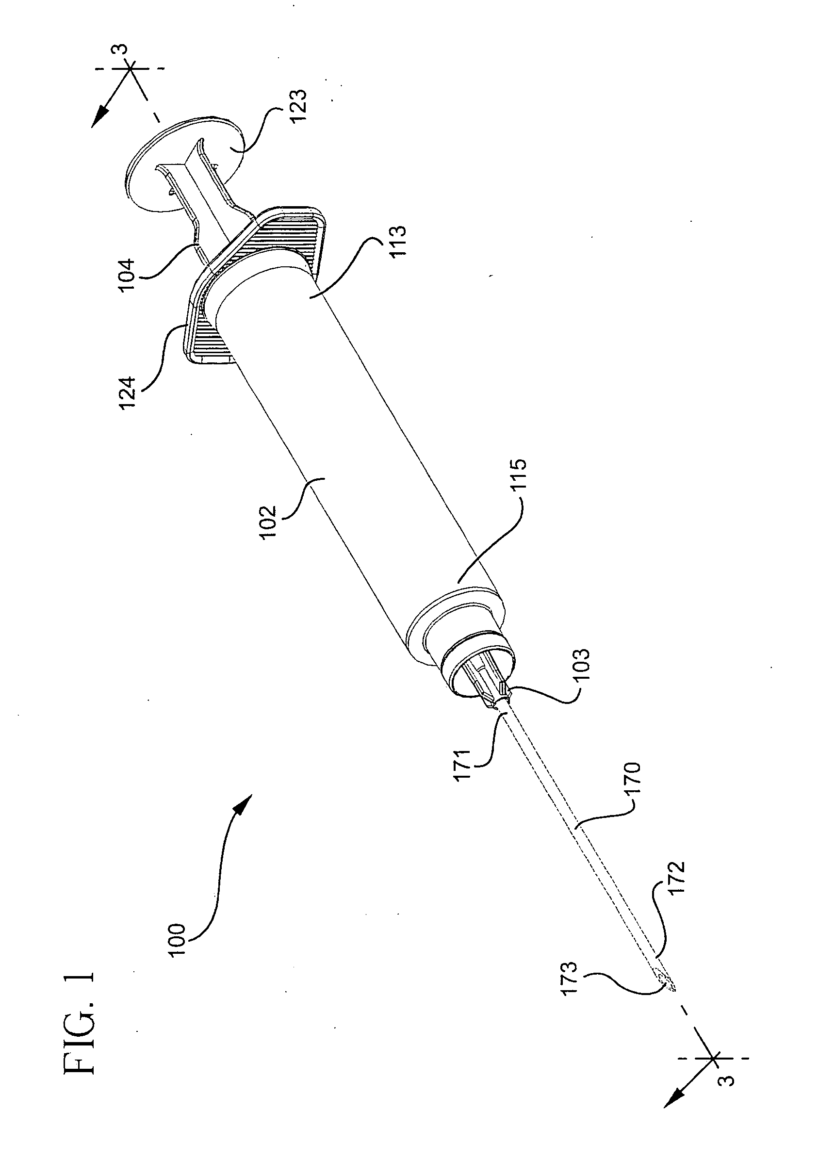
[0039] The present invention is directed to a syringe assembly having a passive disabling mechanism. The disabling mechanism enables variable dosages by the syringe assembly and enables a selected number of cycles or strokes by the plunger rod before being automatically disabled. In one preferred embodiment, the disabling mechanism provides two aspirating and two dispensing cycles before being automatically disabled. The assembly enables the aspiration and dispensing of a selected volume of a diluent into a vial to reconstitute a drug, pharmaceutical agent, or other substance and then aspirating the reconstituted substance back into the syringe. A selected volume of the reconstituted substance can be injected or delivered to a patient where the volume of the substance that is delivered can be the same or different than the volume of the substance aspirated into the syringe barrel. The syringe is automatically disabled after the injection or delivery stroke by retracting the plunger ...


PUM


Abstract

A syringe assembly having passive disabling structure includes a barrel and a plunger rod assembly. The plunger rod assembly includes a plunger rod and a stopper connected by an indexing locking element. The number of strokes of the syringe plunger before the stopper is locked into the barrel rendering the syringe assembly unusable is determined by the number of detents on the plunger rod and stopper which engage the locking mechanism. Upon completion of the final delivery stroke, any attempt to withdraw the plunger rod from the barrel will cause the locking element to engage the barrel and trap the stopper in the barrel preventing further use of the syringe.

Description

[0001] This application claims priority from U.S. Provisional Application No. 60 / 490,939, filed Jul. 30, 2003 and U.S. Provisional Application No. 60 / 523,490, filed Nov. 20, 2003.BACKGROUND OF THE INVENTION [0002] The present invention relates to syringe assemblies and particularly to syringe assemblies having an automatic disabling mechanism. [0003] Throughout the world the multiple use of hypodermic syringe products which are intended for single-use only, is instrumental in drug abuse and in the transfer of contagious diseases. Intravenous drug users who routinely share and re-use syringes are a high-risk group with respect to the AIDS virus. Also, the effects of multiple use are a major concern in some countries where repeated use of syringe products during mass immunization programs may be responsible for the spread of many diseases. Re-use of single-use hypodermic syringe assemblies is also instrumental in the spread of drug abuse even in the absence of infection or disease. [0...

Claims


Application Information

Patent Timeline
IPC IPC(8): A61M5/50
CPCA61M5/5013A61M2005/5033A61M2005/5026A61M5/502
Inventor SURESH, SAMUELSMITH, CHADCAIZZA, RICHARD JAMES
Owner BECTON DICKINSON & CO
Features
  • Generate Ideas
  • Intellectual Property
  • Life Sciences
  • Materials
  • Tech Scout
  • Unparalleled Data Quality
  • Higher Quality Content
  • 60% Fewer Hallucinations
Learn More