Efficient representation of state transition tables

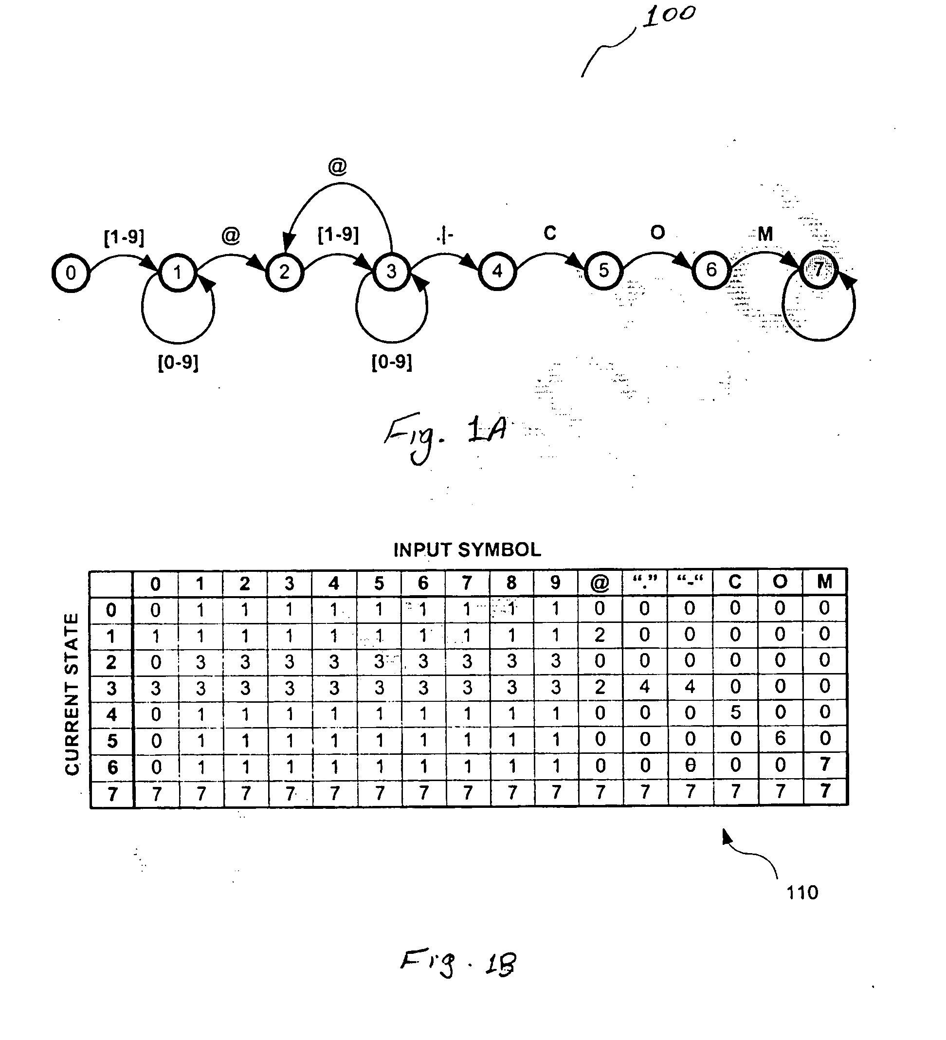
a transition table and state technology, applied in the field of integrated circuits, can solve the problems of sacrificing content delivery or network security, increasing the amount of memory needed to store this data, and qos and signature-based security services are finding it increasingly difficult to keep up with the demands of matching packet content, etc., and achieves high data throughput and small memory.

Inactive Publication Date: 2005-02-03
INTEL CORP +1
View PDF8 Cites 29 Cited by
  • Summary
  • Abstract
  • Description
  • Claims
  • Application Information

AI Technical Summary

Benefits of technology

In accordance with the present invention, the states associated with a programmable finite state machine (FSM), are reordered to compress the transitions that define the FSM. The FSM thus requires a smaller memory while maintaining a high data throughput. The compression is achieved from the redundancy in the state transitions.

Problems solved by technology

As network speeds increase, QoS and signature-based security services are finding it increasingly more challenging to keep up with the demands of the matching packet content.
The services therefore sacrifice content delivery or network security by being required to miss packets.
However as the number of data related to the states, input symbols and transitions become large, the amount of memory needed to store this data grows exponentially.
Programmable FSMs are often expensive because of the size of the memory required to store the transition table.
This problem is even more pronounced for fast FSMs which are required to compute the next state within a few and fixed number of clock cycles.
This technique also suffers from the problem that the stack memory is limited.
Therefore, the transition table may not always be stored efficiently and thus may result in excessive usage of memory resources in high performance hardware.

Method used


Image

  • Efficient representation of state transition tables
  • Efficient representation of state transition tables
  • Efficient representation of state transition tables

Examples


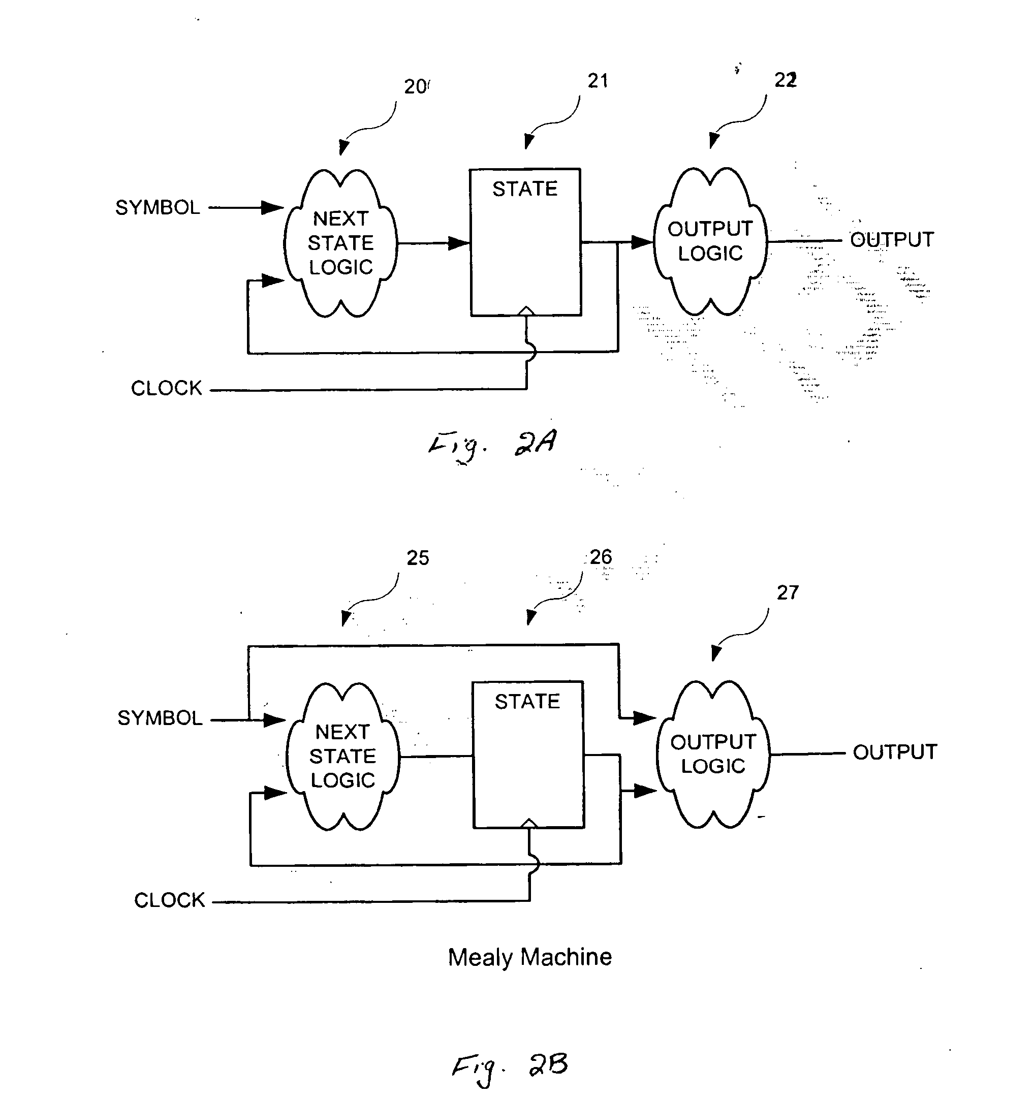
Embodiment Construction

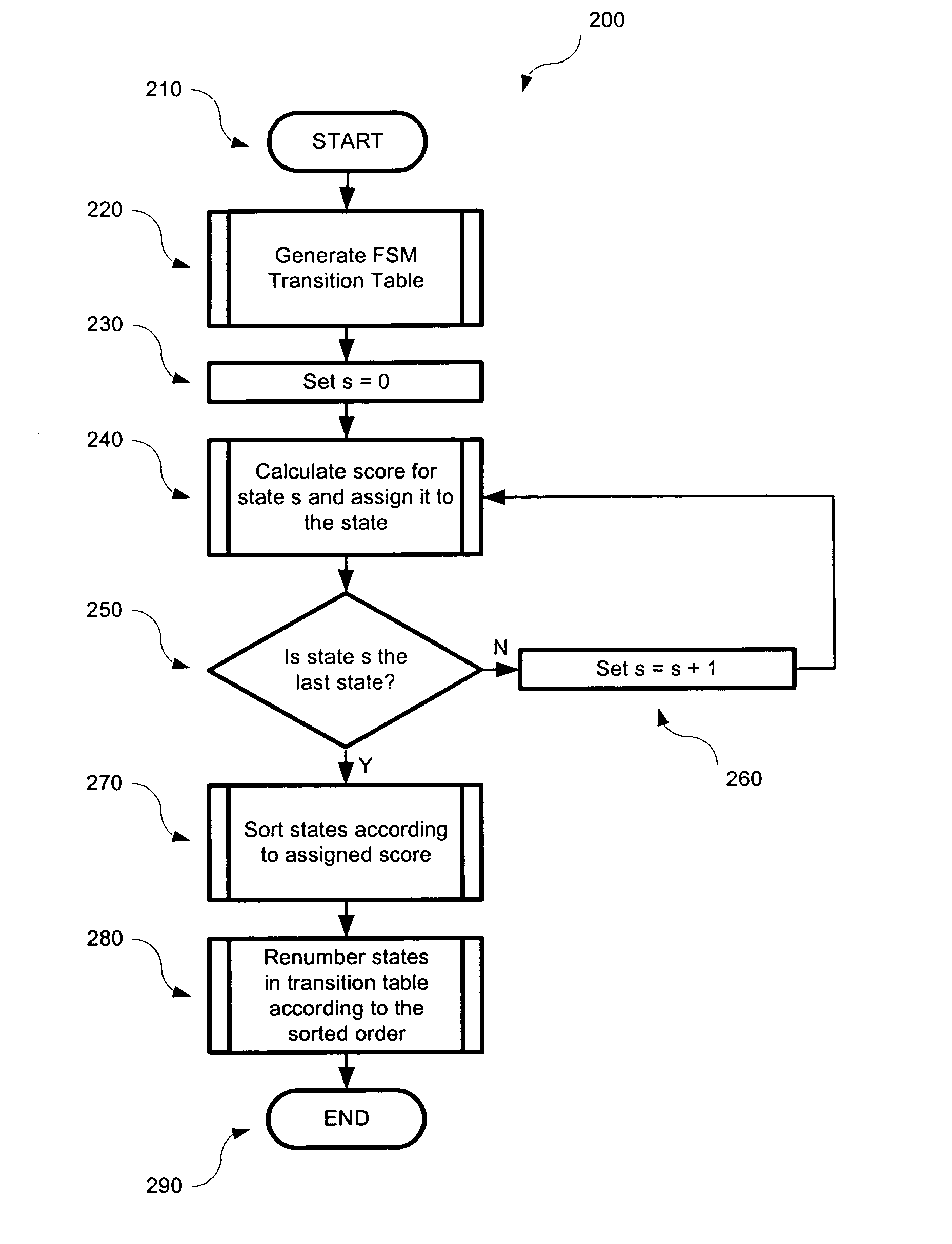
FIG. 4 is a flowchart 200 of steps carried out to renumber the states of a finite state machine (FSM), in accordance with one embodiment of the present invention. At step 210, the renumbering of state begins. At step 220, the transition table associated with the FSM is generated using one of a number of known techniques. At step 230 a parameter s, which keeps track of the states is initialized to 0. Thereafter, a score is computed and assigned to each of the states as iteration is made through steps 240, 250 and 260, and as is seen from the flowchart 200. A number of different techniques may be used to compute these scores, as is described further below.

In step 270, the states are sorted according to their computed scores. In one embodiment, in step 270, the states are sorted according to an ascending order of their computed scores. In another embodiment, the states may be sorted using other sorting algorithms in accordance with their computed scores. In state 280, the states are r...


PUM


Abstract

The states associated with a programmable state machine are reordered to compress the storage of transitions which define the state machine. To reorder the states, a score is computed and assigned to each of the states. Next, the states are sorted according to their computed scores. In some embodiments, to compute the score for each current state based on the received input symbol, the number of times that the input symbol causes transition to similar states is added. The sum of the scores in each row of the table is representative of the score for the associated current state associated with that row. The states are sorted according to their score and a new state transition table is generated in accordance with the reordered states.

Description

FIELD OF THE INVENTION The present invention relates to integrated circuits, and more particularly to programmable finite state machines with high throughput. BACKGROUND OF THE INVENTION Deep content inspection of network packets is driven, in large part, by the need for high performance quality-of-service (QoS) and signature-based security systems. Typically QoS systems are configured to implement intelligent management and deliver content-based services which, in turn, involve high-speed inspection of packet payloads. Likewise, signature-based security services, such as intrusion detection, virus scanning, content identification, network surveillance, spam filtering, etc., involve high-speed pattern matching on network data. The signature databases used by these services are updated on a regular basis, such as when new viruses are found, or when operating system vulnerabilities are detected. This means that the device performing the pattern matching must be programmable. As ne...

Claims


Application Information

Patent Timeline
Patent Type & Authority Applications(United States)
IPC IPC(8): G06FG06F7/38G06F9/44G06F17/50H01L
CPCG06F9/444G06F9/4498
Inventor GOULD, STEPHENBARRIE, ROBERT MATTHEWFLANAGAN, MICHAELWILLIAMS, DARREN
Owner INTEL CORP
Why Eureka
Try Eureka