
Ultrahigh-speed compression photographing device based on compression perception and streak camera principles

A stripe camera and photographic device technology, applied to color TV parts, TV system parts, TVs, etc., can solve the problems of limited practical application and limited imaging speed, and achieve the improvement of reconstructed image quality and low memory consumption. Highly secure, small memory footprint

Active Publication Date: 2017-09-26
EAST CHINA NORMAL UNIV
View PDF7 Cites 6 Cited by
  • Summary
  • Abstract
  • Description
  • Claims
  • Application Information

AI Technical Summary

Problems solved by technology

Although this sensor has a very wide range of influences and applications, the imaging speed based on CCD and CMOS technology is limited by the chip storage and electronic readout speed, so it is impossible to further increase the imaging speed, which limits the practical application of many related fields. , such as measuring the speed of light or moving objects close to the speed of light

Method used


Image

  • Ultrahigh-speed compression photographing device based on compression perception and streak camera principles
  • Ultrahigh-speed compression photographing device based on compression perception and streak camera principles
  • Ultrahigh-speed compression photographing device based on compression perception and streak camera principles

Examples


Embodiment

[0030] In this embodiment, the luminescent process of a single nanoparticle is simulated.

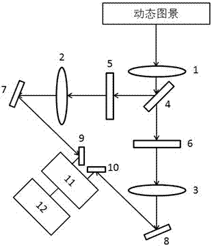
[0031] The components of this embodiment refer to figure 1 set up. The light reaches the beam splitter 4 through the first lens 1, and then splits into two to become two lines of light with equal intensity, and the reflected one reaches the second lens 2 after being modulated by the first spatial light modulator 5. Similarly, The transmitted one reaches the third lens 3 after being modulated by the second spatial light modulator 6. By placing four plane mirrors 7, 8, 9, and 10, both paths of light enter the streak camera 11 with a built-in CCD, and finally the decoder 12 Receive the image captured by the built-in CCD of the streak camera, and use the TwIST algorithm to decode and reconstruct the image.

[0032] The working process of this embodiment:

[0033]The high-speed dynamic scene is first imaged by the first lens 1, and then reaches the beam splitter 4 to form two optical path...


PUM


Abstract

The invention provides an ultrahigh-speed compression photographing device based on compression perception and streak camera principles. The device comprises a lens, a beam splitter, a spatial light modulator, a flat mirror, a streak camera with a built-in CCD, and a decoder. Firstly, captured image information is coded through the spatial light modulator. Then the streak camera is utilized for superposing image information at different time points and performing compression sampling. Finally reconstruction is performed on the image based on a compression perception principle. According to the device, two-dimensional imaging can be performed on an ultrafast process on the condition of definite imaging speed of the streak camera; the image information is output to a decoder; a two-dimensional image dynamic process (x-y-t) is reconstructed through a TwIST algorithm; and the imaging speed can reach 10-12 frame / second. The ultrahigh-speed compression photographing device utilizes single-time photographing measuring technology which can measure un-repeated ultrafast events.

Description

technical field [0001] The invention belongs to the field of ultrafast imaging technology, and relates to a two-dimensional image measurement technology that can be used for nanosecond and picosecond ultrafast physical, chemical, biological and other processes, and can be used to measure picosecond laser pulses of arbitrary shape in the time-frequency domain , observe the dynamic process of micro-nano processing, analyze the dynamic process of molecular structure change under strong light field, etc. Background technique [0002] Capturing images of transient scenes at high speed has always been the dream and goal of photographers. The most typical early examples are the recording of running horses in 1878 and supersonic bullet photography in 1887. However, until the end of the twentieth century, this ultra-high-speed imaging still had not been broken through, when the imaging speed was 10^5 frames per second. Later, with the emergence of electronic imaging sensors based on...

Claims


Application Information

Patent Timeline
Patent Type & Authority Applications(China)
IPC IPC(8): H04N5/225
CPCH04N23/54H04N23/50H04N23/55
Inventor 曹烽燕杨承帅孙真荣张诗按
Owner EAST CHINA NORMAL UNIV
Learn More