
Gutter guard

a technology of gutter guards and gutters, applied in the field of gutter guards, can solve the problems of many of these gutter guards not working as desired, and the concept does not always work,

Active Publication Date: 2005-02-10
ALCOA HOME EXTERIORS +10
View PDF9 Cites 23 Cited by
  • Summary
  • Abstract
  • Description
  • Claims
  • Application Information

AI Technical Summary

Benefits of technology

[0010] The device of the present invention provides a guard for the eaves trough to prevent foreign matter from entering into the eaves trough. This is achieved by means of appropriate sizing of the apertures formed therein. In this respect, the aperture size and aperture placement must permit adequate drainage of the water through the apertures into the eaves trough while substantially excluding any foreign matter which remains on the top and which normally would be removed by the element of wind and the like. Adequate sizing of the apertures will prevent clogging of the device.
[0013] As will be appreciated, during a period of heavy rain, the drainage might not be instantaneous and accordingly, there is preferably provided a vertically extending wall adjacent the front wall of the gutter to prevent overflow.
[0016] In the present invention, the device may be provided with a flexible sealing strip which is retained by the device and is designed above the adjoining structure to prevent water seeping between the gutter and support structure.

Problems solved by technology

However, many of these guards do not function as desired and access must still be had to the eaves trough for cleaning purposes.
However, this concept does not always work when the volume of water becomes sufficiently large so that the surface tension is not sufficient to cause all the water to flow into the gutter.

Method used


Image

  • Gutter guard
  • Gutter guard
  • Gutter guard

Examples


Embodiment Construction

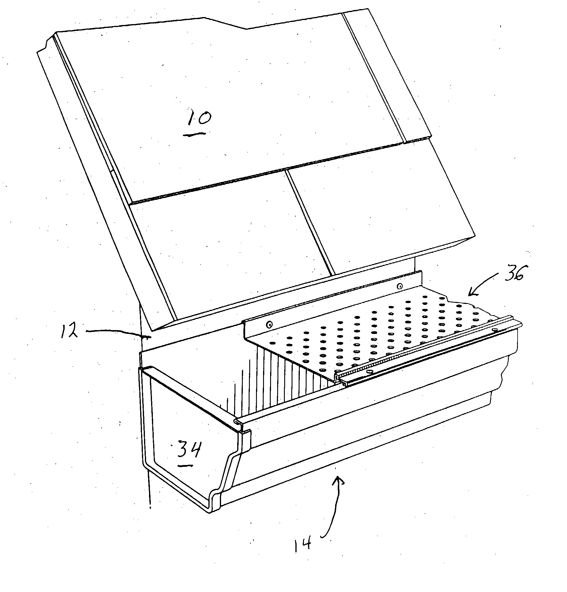
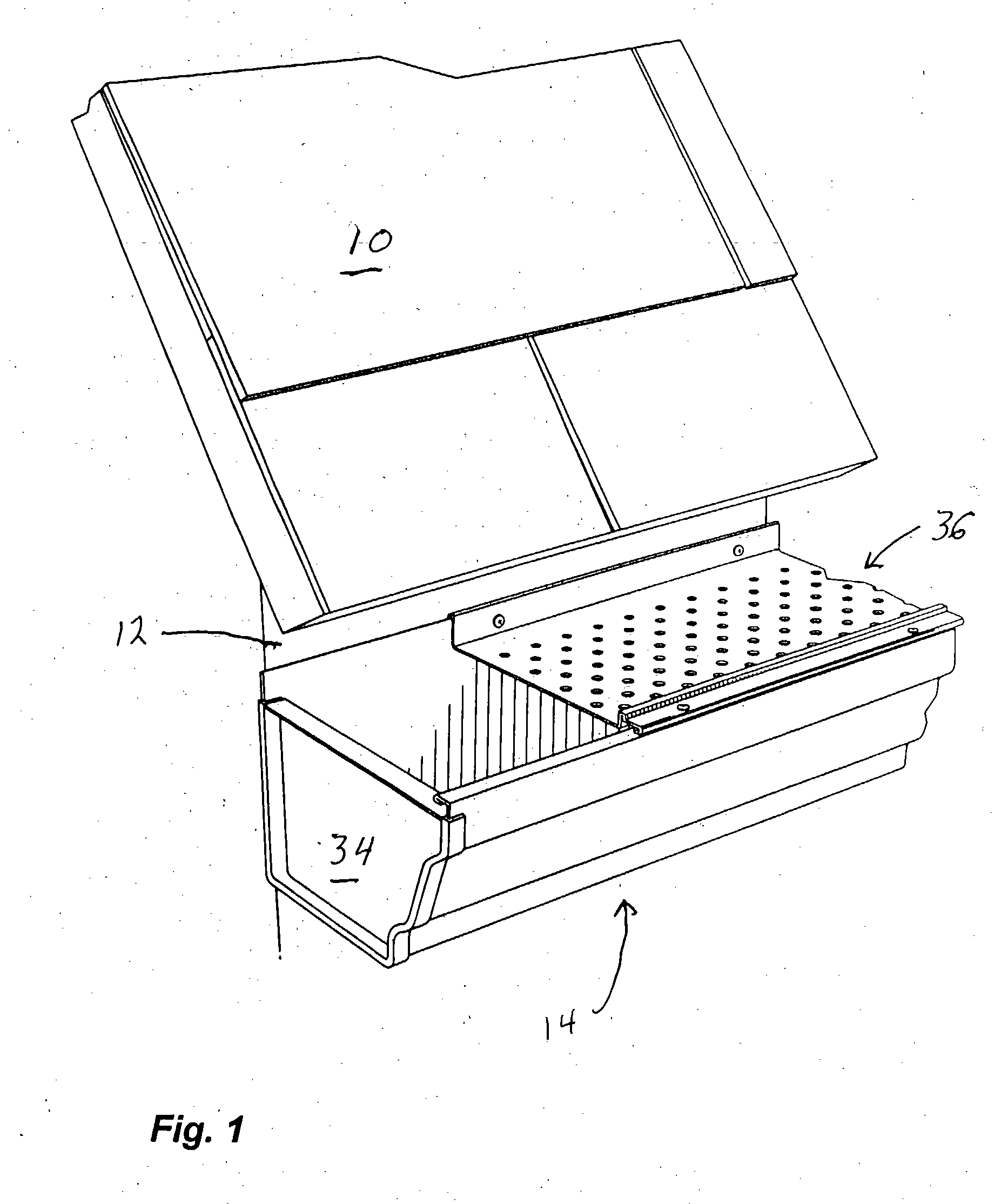
[0025] Referring to the drawings in a greater detail and by reference characters thereto, there is illustrated in FIG. 1 a portion of a gutter generally designated by reference numeral 14 and which is attached to a supporting structure 12 to receive run-off from roof 10.

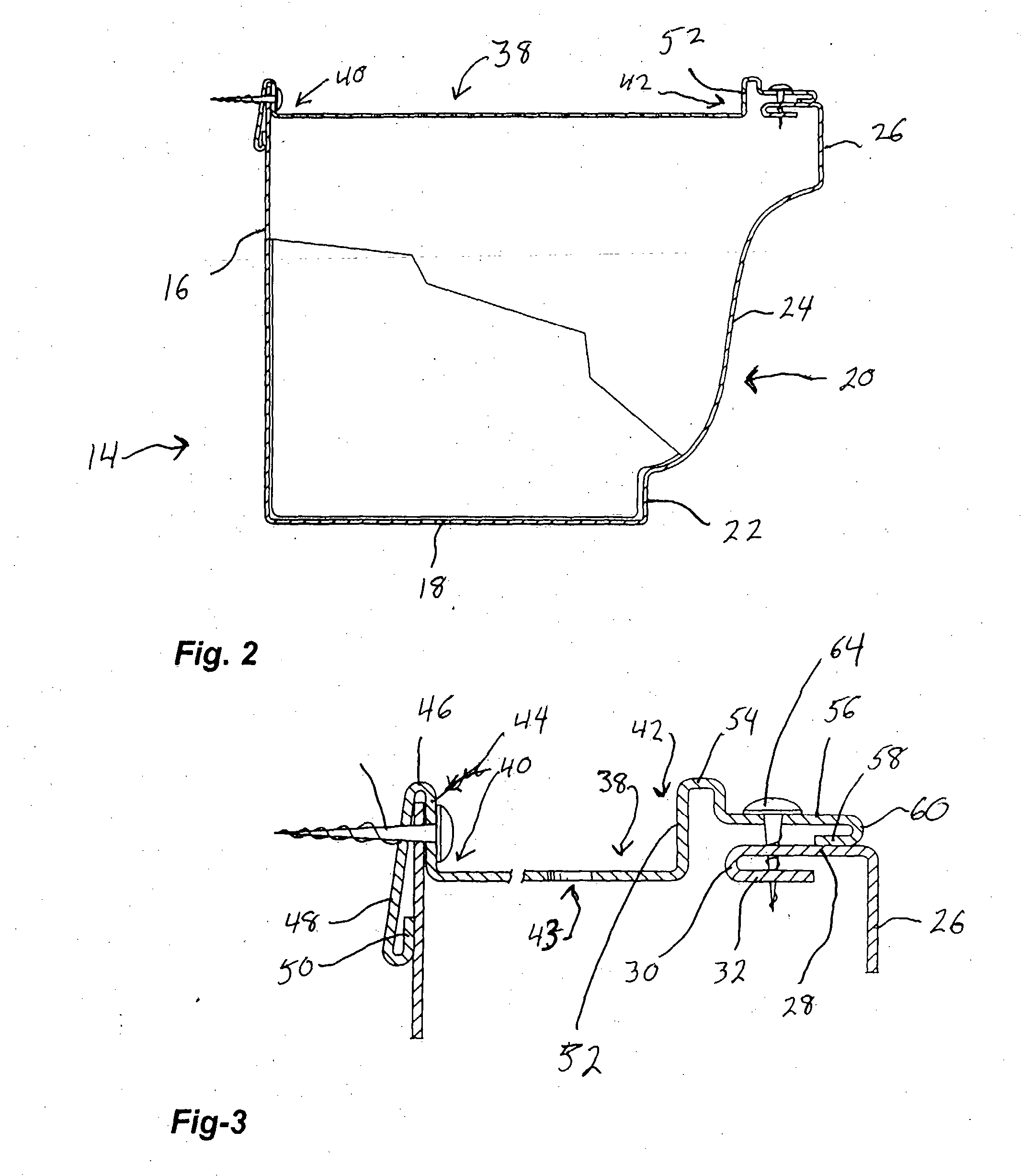
[0026] Gutter 14 is of a conventional design which is widely available in the market place and has a back wall 16 which is designed to lie substantially adjacent to the supporting structure 12. Extending between a front row 20 and back wall 16 is a bottom 18. Front wall 20 includes a lower vertical segment 22, a central arcuate segment 24 and upper vertical segment 26. As may be best seen in FIG. 3, at the upper end of upper vertical segment 26, there is provided an inwardly extending flange 28 and a reversely extending lower flange 32 connected thereto by means of a bight 30. As seen in FIG. 1, a conventional end cap 34 is utilized to seal the end of gutter 14.

[0027] According to this embodiment of the present inv...


PUM


Abstract

A device for protecting a gutter having a rear wall, front wall and a bottom wall, the walls defining a trough there between, the device comprising a guard member having generally planar central portion with one side thereof having an inverted U-shaped configuration designed to fit over an upper marginal edge of the rear wall of the gutter while at the other side, there is provided an overflow wall. The guard and gutter are attached directly to a supporting structure by means of screws or other mechanical fastening devices.

Description

FIELD OF THE INVENTION [0001] The present invention relates to a shield for a rain water gutter assembly also known as an eaves trough. BACKGROUND OF THE INVENTION [0002] The use of shields for gutters or eaves troughs is well know in the prior art and many patents have issued for different types of shields. The purpose of the gutter shield is essentially to permit passage of rain water from the roof to the gutter or eaves trough while protecting the same from extraneous foreign matter such as leaves and the like, which could lead to clogging. [0003] In practice, the use of a shield or a guard comprises a member which is apertured and permits the passage of rain water while banning the passage of extraneous material into the gutter. The shields or guards are attached in various manners to a portion to the gutter. However, many of these guards do not function as desired and access must still be had to the eaves trough for cleaning purposes. [0004] It is also been proposed in the art ...

Claims


Application Information

Patent Timeline
IPC IPC(8): E04D13/076
CPCE04D13/076
Inventor BROCHU, GUY
Owner ALCOA HOME EXTERIORS
Learn More