Printing systems and methods using keyless inking and continuous dampening

a printing system and dampening technology, applied in office printing, rotary letterpress machines, rotary intaglio printing presses, etc., can solve problems such as color control and ink feedback loss into dampening fluid reservoirs, and the solution has not been completely successful in solving these problems

Inactive Publication Date: 2005-02-10
PRICE JAMES F
View PDF74 Cites 31 Cited by
  • Summary
  • Abstract
  • Description
  • Claims
  • Application Information

AI Technical Summary

Problems solved by technology

When the form roller in the inker engages the printing plate, the ink film on the form roller contacting image areas on the printing plate is split such that approximately one-half of the thickness of the ink film is applied to the image area of the printing plate leaving approximately one-half the ink on the form roller that never recovers its original ink film thickness on the printed, ink depleted areas causing a condition referred to as starvation.
This combination of accumulation and starvation results in undesirable “ghosted” images and image repeats being formed on the final printed product.
However, these solutions have not been completely successful in solving these problems.
For example, some undesirable “tinting” in the non-image areas has been observed to occur when the system is used with some standard inks formulated for multiple form roll applications.
Newspaper printers have generally avoided continuous dampening for a number of reasons, including the fact that the standard and keyless inking systems have no means of preventing uncontrollable accumulation of ink and fountain solution in the inkers resulting in lost color control and ink feedback into the dampening fluid reservoir.

Method used


Image

  • Printing systems and methods using keyless inking and continuous dampening
  • Printing systems and methods using keyless inking and continuous dampening
  • Printing systems and methods using keyless inking and continuous dampening

Examples


Embodiment Construction

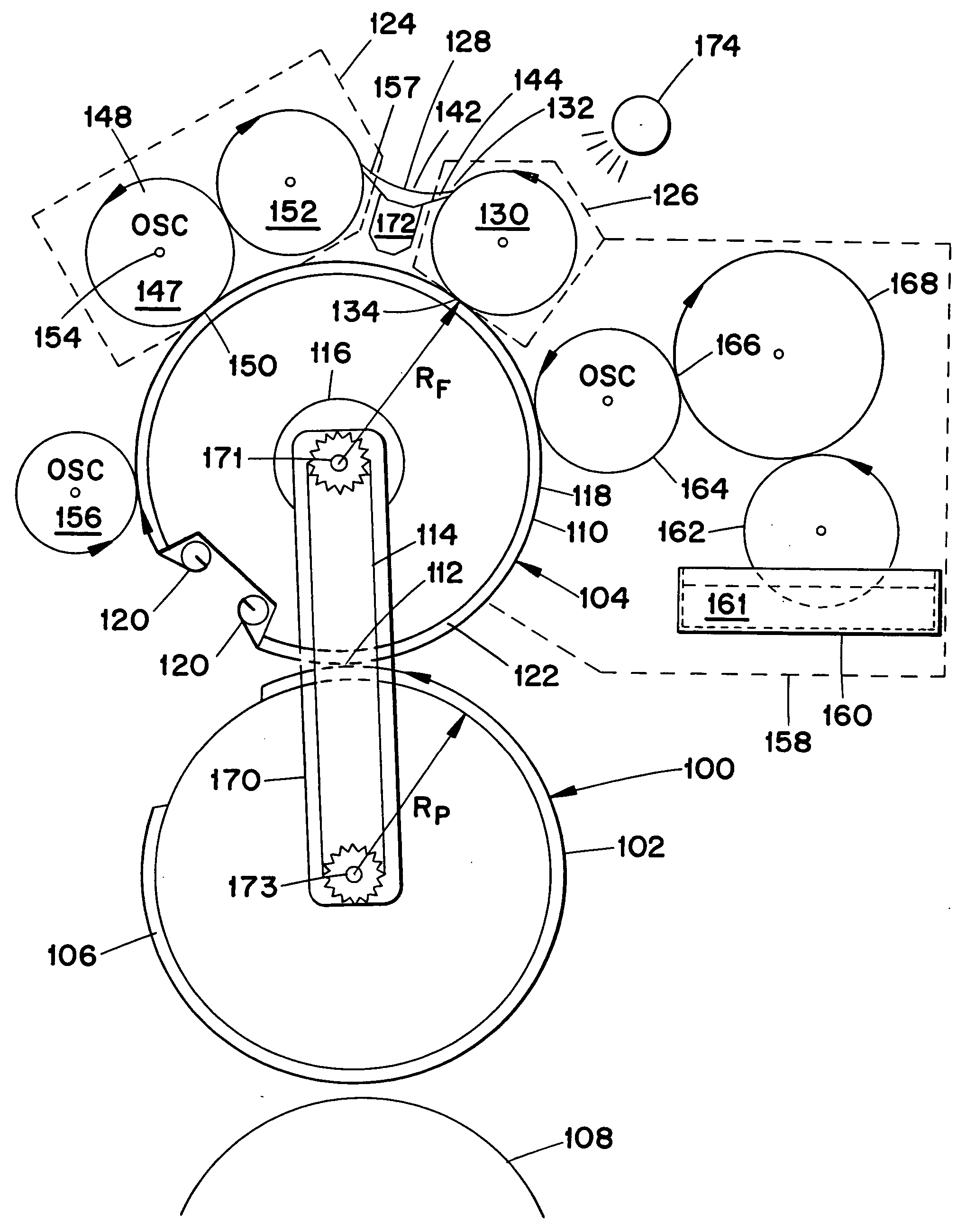
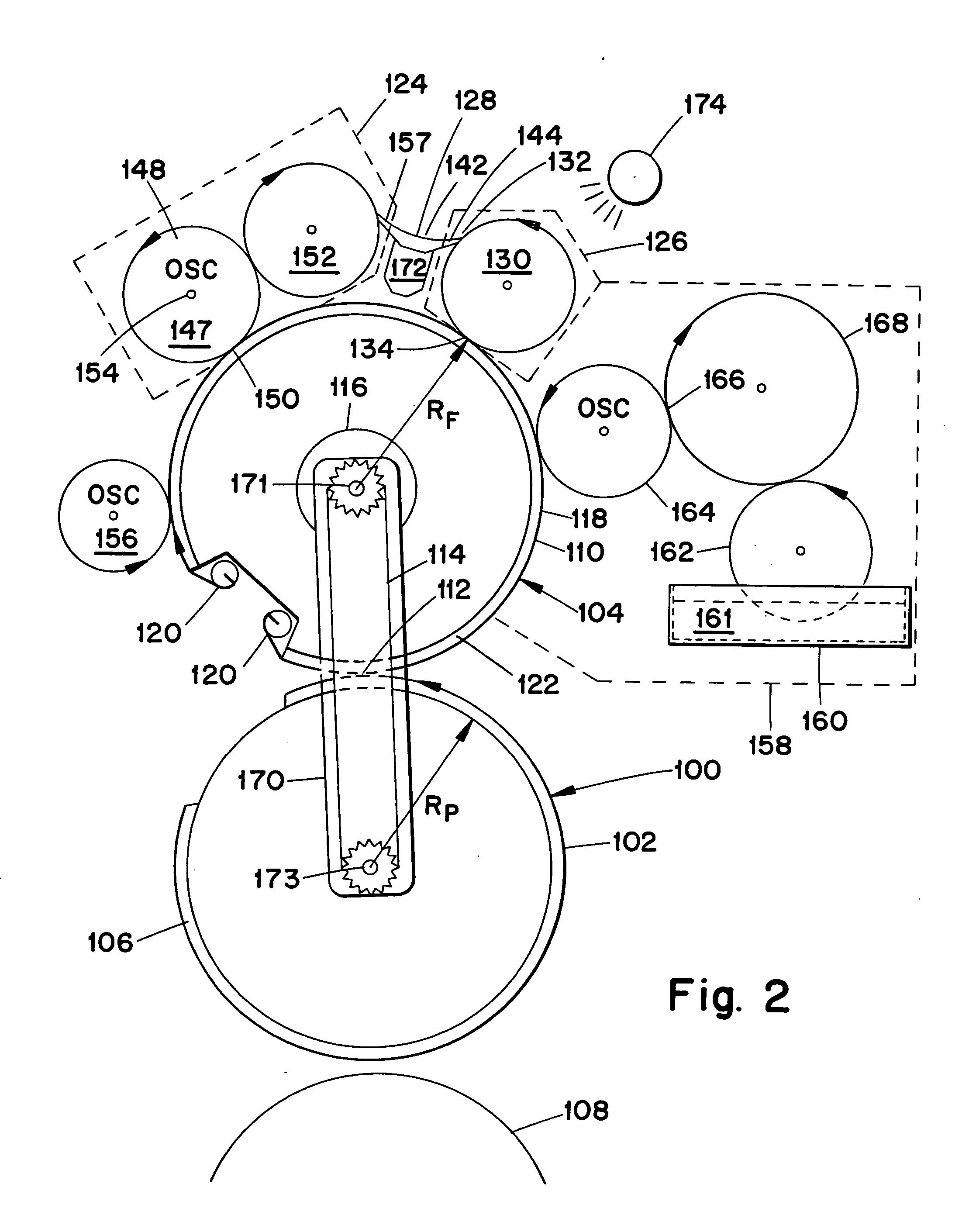
[0013] The inking systems disclosed herein employ at least one form roller in contact with the printing plate cylinder. Another roller may contact the plate and remove residual ink from non-image areas of the plate surface. A subtractive roller system, which contacts the at least one form roller, removes excess ink and dampening solution from the form roller after printing. An applicator roller then applies the necessary ink film to maintain desired color to the form roller. A continuous duty dampening system then continuously resupplies the required amount of dampening fluid as required by the ink film on the form roller.

[0014] Preferred embodiments of the present invention include a printing system having a rotating plate cylinder carrying a printing plate and a main form roller for applying ink to the printing plate. In accordance with this aspect of the invention the plate cylinder and the form roller are rotated at the same rpm so that the same areas on the form roller contact...


PUM


Abstract

Keyless inking and dampening systems and methods are disclosed which employ application, subtractive and dampening roller systems to control the ink / dampening fluid film on the form roller. A clean-up roller removes residual ink from non-image areas on the printing plate.

Description

RELATED APPLICATIONS [0001] The patent application is a continuation in part of U.S. application Ser. No. 10 / 617,017 filed Jul. 11, 2003, and a continuation in part of U.S. application Ser. No. 10 / 720,254 filed Nov. 25, 2003, which is a divisional of U.S. application Ser. No. 09 / 813,887 filed Mar. 22, 2001, now U.S. Pat. No. 6,672,211, which is a continuation in part of U.S. application Ser. No. 09 / 507,549 filed Feb. 18, 2000, now U.S. Pat. No. 6,571,710, issued on Jun. 3, 2003, and claims the benefit of U.S. Provisional Application No. 60 / 122,765 filed. Mar. 3, 1999, all of which prior applications are hereby incorporated by reference in their entirety.FIELD OF THE INVENTION [0002] The field of the invention is inking systems and methods for printing presses for uniformly applying ink and / or dampening fluid to the printing plates and removing unwanted ink from the printing plates, especially from non-image areas. BACKGROUND OF THE INVENTION [0003] An offset printing press typically...

Claims


Application Information

Patent Timeline
Patent Type & Authority Applications(United States)
IPC IPC(8): B41FB41F9/00B41F31/00B41F31/20
CPCB41F31/004B41P2235/22B41P2231/20B41F31/20
Inventor PRICE, JAMES F.GOODMAN, ROBERT L.DAHLGREN, MAX W.
Owner PRICE JAMES F
Why Eureka
Try Eureka