Parallel Array Architecture for a Graphics Processor

a graphics processor and parallel array technology, applied in the field of parallel array architecture for graphics processors, can solve the problems of increasing the load on the vertex shader core, reducing the memory locality, and reducing the efficiency of the graphics processing

Inactive Publication Date: 2007-07-12
NVIDIA CORP
View PDF12 Cites 129 Cited by
  • Summary
  • Abstract
  • Description
  • Claims
  • Application Information

AI Technical Summary

Benefits of technology

[0010] In embodiments where a pixel shader program is to be executed, the cluster or core in which the program is to be executed is advantageously selected based on the location of the pixel within the image area. In one embodiment, the screen is tiled, with each tile being assigned to one or another of the processing clusters (or to a specific core within a processing cluster). The tiles assigned to a given processing cluster or core are advantageously scattered across the screen to provide approximate load balancing.
[0011] In some embodiments, the processing core or cluster includes a raster operations unit that integrates newly generated pixel data with existing data in a frame buffer. The frame buffer can be partitioned to match the number of processing clusters, with each cluster writing all of its data to one partition. In other embodiments, the number of partitions of the frame buffer need not match the number of processing clusters in use. A crossbar or similar circuit structure may provide a configurable coupling between the processing clusters and the frame buffer partitions, so that any processing cluster can be coupled to any frame buffer partitions; in some embodiments, the crossbar is omitted, improving memory locality.

Problems solved by technology

SIMD machines generally have advantages in chip area (since only one instruction unit is needed) and therefore cost; the downside is that parallelism is only available to the extent that multiple instances of the same instruction can be executed concurrently.
First, the separate processing cores for vertex and shader programs are separately designed and tested, often leading to at least some duplication of effort.
Second, the division of the graphics processing load between vertex operations and pixel operations varies greatly from one application to another.
As is known in the art, detail can be added to an image by using many small primitives, which increases the load on the vertex shader core, and / or by using complex texture-mapping and pixel shading operations, which increases the load on the pixel shader core.
In most cases, the loads are not perfectly balanced, and one core or the other is underused.
In either case, some fraction of available processing cycles is effectively wasted.

Method used


Image

  • Parallel Array Architecture for a Graphics Processor
  • Parallel Array Architecture for a Graphics Processor
  • Parallel Array Architecture for a Graphics Processor

Examples


Embodiment Construction

System Overview

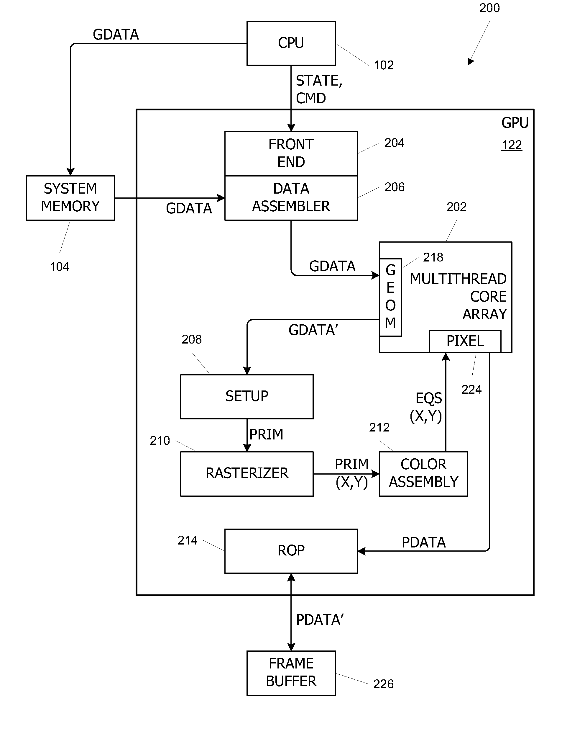
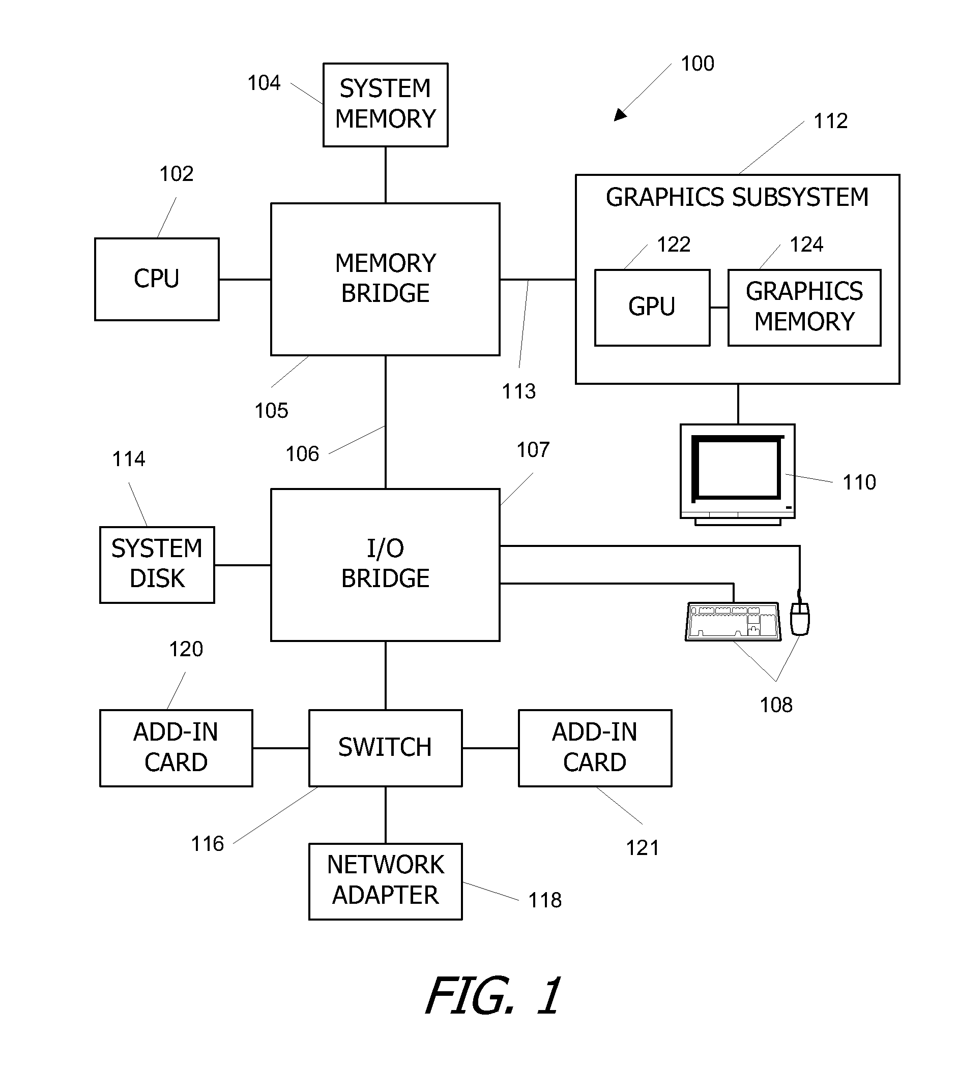
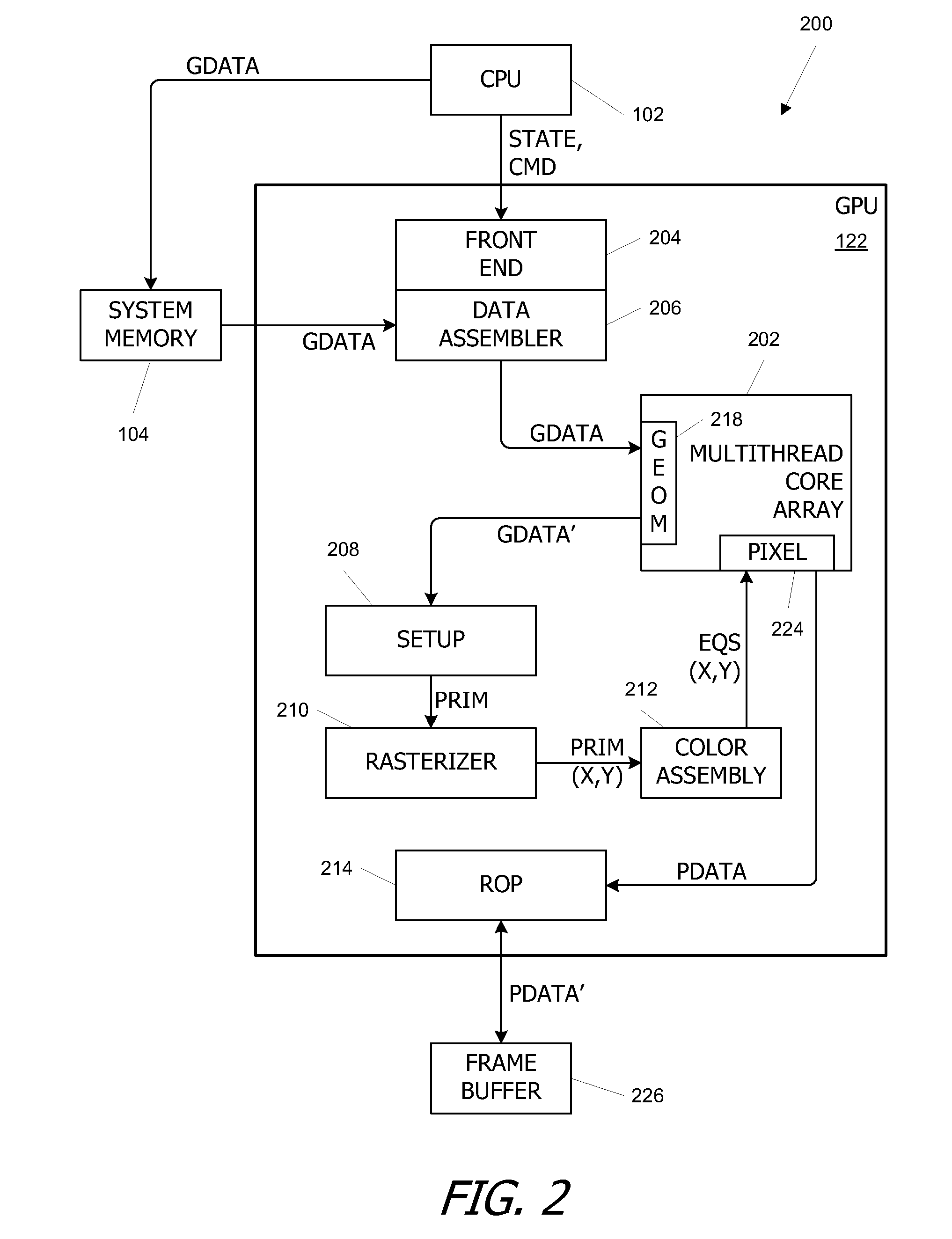
[0019]FIG. 1 is a block diagram of a computer system 100 according to an embodiment of the present invention. Computer system 100 includes a central processing unit (CPU) 102 and a system memory 104 communicating via a bus path that includes a memory bridge 105. Memory bridge 105 is connected via a bus path 106 to an I / O (input / output) bridge 107. I / O bridge 107 receives user input from one or more user input devices 108 (e.g., keyboard, mouse) and forwards the input to CPU 102 via bus 106 and memory bridge 105. Visual output is provided on a pixel based display device 110 (e.g., a conventional CRT or LCD based monitor) operating under control of a graphics subsystem 112 coupled to memory bridge 105 via a bus 113. A system disk 114 is also connected to I / O bridge 107. A switch 116 provides connections between I / O bridge 107 and other components such as a network adapter 118 and various add-in cards 120, 121. Other components (not explicitly shown), including USB or ...


PUM


Abstract

A parallel array architecture for a graphics processor includes a multithreaded core array including a plurality of processing clusters, each processing cluster including at least one processing core operable to execute a pixel shader program that generates pixel data from coverage data; a rasterizer configured to generate coverage data for each of a plurality of pixels; and pixel distribution logic configured to deliver the coverage data from the rasterizer to one of the processing clusters in the multithreaded core array. The pixel distribution logic selects one of the processing clusters to which the coverage data for a first pixel is delivered based at least in part on a location of the first pixel within an image area. The processing clusters can be mapped directly to the frame buffers partitions without a crossbar so that pixel data is delivered directly from the processing cluster to the appropriate frame buffer partitions. Alternatively, a crossbar coupled to each of the processing clusters is configured to deliver pixel data from the processing clusters to a frame buffer having a plurality of partitions. The crossbar is configured such that pixel data generated by any one of the processing clusters is deliverable to any one of the frame buffer partitions.

Description

CROSS-REFERENCES TO RELATED APPLICATIONS [0001] The present application claims the benefit of U.S. Provisional Application No. 60 / 752,265, filed Dec. 19, 2005, which is incorporated herein by reference in its entirety for all purposes. [0002] The present application is related to the following commonly-assigned co-pending U.S. patent applications: application Ser. No. 11 / 290,303, filed Nov. 29, 2005; application Ser. No. 11 / 289,828, filed Nov. 29, 2005; and application Ser. No. 11 / 311,993, filed Dec. 19, 2005, which are incorporated in their entirety, herein, by reference for all purposes.BACKGROUND OF THE INVENTION [0003] The present invention relates in general to graphics processors, and in particular to a parallel array architecture for a graphics processor. [0004] Parallel processing techniques enhance throughput of a processor or multiprocessor system when multiple independent computations need to be performed. A computation can be divided into tasks that are defined by progra...

Claims


Application Information

Patent Timeline
Patent Type & Authority Applications(United States)
IPC IPC(8): G06F15/80G06T15/00
CPCG06T15/005G06T2210/52G09G2360/122G09G5/393G09G2360/06G09G5/363G06F15/80G06F15/8015G06F15/76G06T1/00
Inventor DANSKIN, JOHN M.MONTRYM, JOHN S.LINDHOLM, JOHN ERIKMOLNAR, STEVEN E.FRENCH, MARK
Owner NVIDIA CORP
Why Eureka
Try Eureka