Lubricating and cooling structure of wet type friction engagement apparatus

a friction engagement and cooling structure technology, applied in the direction of fluid actuated brakes, non-mechanical actuated clutches, braking elements, etc., can solve the problems of reducing efficiency, drag loss, and increasing the driving force of oil pumps, so as to improve fuel efficiency and reduce the drag torque of wet-type friction engagement apparatus in the usual state of us

Inactive Publication Date: 2005-02-10
DAINATSUKUSU
View PDF4 Cites 18 Cited by
  • Summary
  • Abstract
  • Description
  • Claims
  • Application Information

AI Technical Summary

Benefits of technology

[0020] According to the present invention, an inner surface of a hub is in a stepped taper shape wherein its diameter increases toward its opening so that lubricating oil can be leaked from the opening end. Therefore, a large amount of lubricating oil can be drained during low-speed rotation, and as a result, the drag torque of a wet-type friction engaging apparatus in a usual state of use is reduced and fuel efficiency is improved.

Problems solved by technology

However, since such a wet-type friction engaging apparatus 10A needs to be supplied a large amount of lubricating oil B in order to heighten the cooling effect of the friction disk 30 and the mating plate 40, and it causes a problem such that the driving force of an oil pump (not shown) has to be increased.
In addition, if the amount of supply of lubricating oil B is increased in order to heighten the cooling effect, lubricating oil B is regularly churned by the friction disk 30 or the mating plate 40 in the releasing state of the wet-type friction engaging apparatus 10A, and it causes a problem that fuel efficiency would worsen due to so-called “friction loss”.
Therefore, in a usual state of use, a drag torque is generated due to the viscosity of the lubricating oil B and this causes drag loss and lowering of efficiency.
However, the lubrication and cooling structure of Patent Document 1 has a difficulty of miniaturizing a wet-type friction engagement apparatus since its structure is complicated and a lot of structural elements are required so as to realize its function.

Method used


Image

  • Lubricating and cooling structure of wet type friction engagement apparatus
  • Lubricating and cooling structure of wet type friction engagement apparatus
  • Lubricating and cooling structure of wet type friction engagement apparatus

Examples


Embodiment Construction

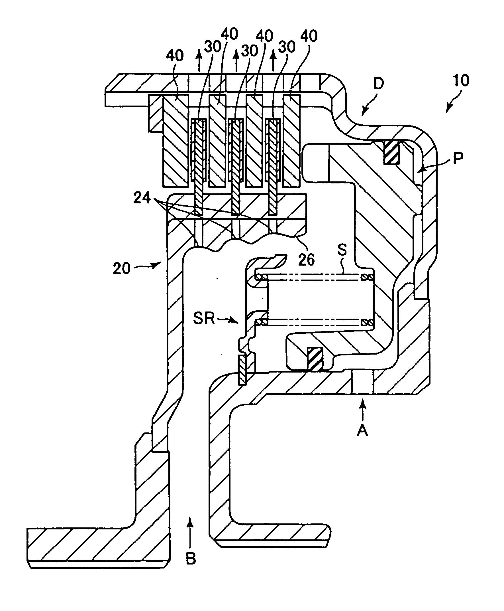
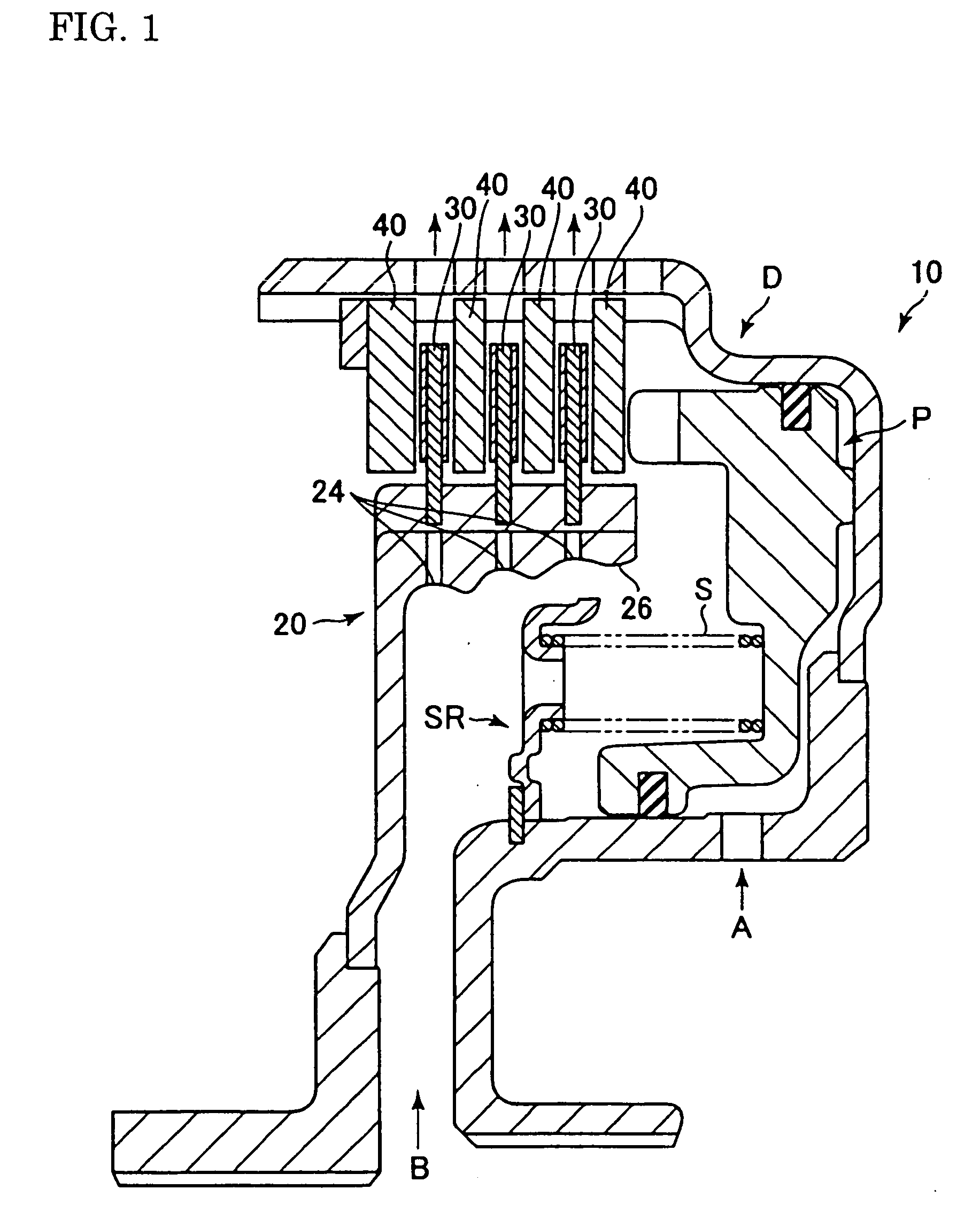
[0026] Embodiments of the present invention will be explained referring to FIG. 1.

[0027] As shown in FIG. 1, a wet-type friction engaging apparatus 10 comprises a friction disk 30 which is fitted by spline with a hub 20 and a mating plate 40 which is fitted by spline with a drum D. The friction disk 30 and the mating plate 40 are arranged alternately, and torque is transmitted when the friction disk 30 and the mating plate 40 are engaged with each other.

[0028] The drum D houses a piston P, which is thrust by operating oil A, pressing the friction disk 30 and the mating plate 40 to be in press contact with each other, and a spring receiver SR, which receives a spring S driving the piston P away from the friction disk 30 and the mating plate 40.

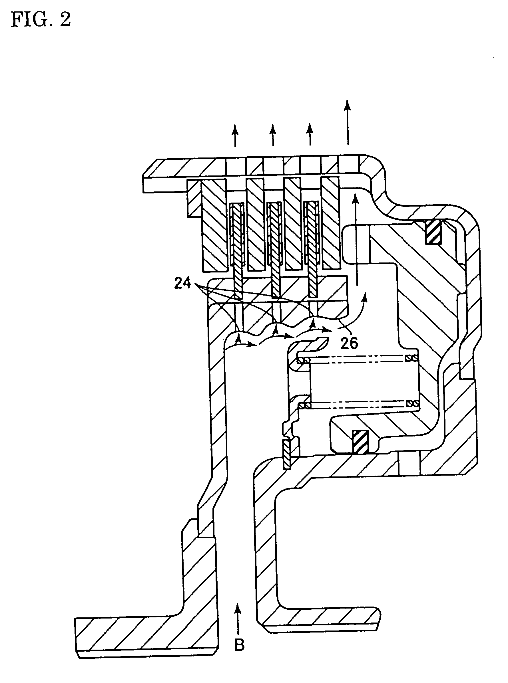
[0029] The inner surface of a hub 20 is in a stepped taper shape in order to let lubricating oil B leak from an opening end 26 of the hub 20, and an oil bore 24 is provided in each step in a radial direction of the hub 20. A periphery of an ...


PUM


Abstract

A wet-type friction engaging apparatus 10 comprises a friction disk 30 which is fitted by spline with a hub 20 and a mating plate 40 which is fitted by spline with a drum D. The friction disk 30 and the mating plate 40 are arranged alternately, and torque is transmitted when the friction disk 30 and the mating plate 40 are engaged with each other. The inner surface of the hub 20 is in a stepped taper shape in order to let lubricating oil B leak from an opening end 26 of the hub 20, and an oil bore 24 is provided in each step in a radial direction of the hub 20. A periphery of an inlet of each oil bore 24 is in a concave shape. During low-speed rotation when centrifugal force is relatively small, the lubricating oil B leaks from the opening end 26 of the hub 20 and drag torque is reduced, and during high-speed rotation when centrifugal force is relatively large, lubricating oil which splashes from a shaft is securely concentrated and then be drained through the oil bore 24.

Description

FIELD OF THE INVENTION [0001] The present invention relates to a structure, which enables to lubricate and cool down an engaging section by efficiently supplying cooling / lubricating nil to a wet-type friction engaging apparatus used in a transmission for a motor vehicle or in a transmission for an industrial or construction machinery. BACKGROUND OF THE INVENTION [0002] Conventionally, a wet-type friction engaging apparatus has been used in such as an automatic transmission for a motor vehicle or a transmission for an industrial or construction machinery etc. as a apparatus to transmit torque or to turn off its transmission. [0003] As shown in FIG. 4, a friction disk 30 and a mating plate 40 are arranged alternately in a drum D of a wet-type friction engaging apparatus and the drum D houses a piston P, which is thrust by operating oil A, pressing the friction disk 30 and the mating plate 40 to be in press contact with each other, and a spring receiver SR, which receives a spring S dr...

Claims


Application Information

Patent Timeline
Patent Type & Authority Applications(United States)
IPC IPC(8): F16D65/853F16D25/0638F16D25/12F16D55/40
CPCF16D25/123F16D25/0638
Inventor KITABAYASHI, HISANAO
Owner DAINATSUKUSU
Why Eureka
Try Eureka