Direct current detection circuit

a detection circuit and direct current technology, applied in the direction of earth fault current switch, measurement using dc-ac conversion, instruments, etc., can solve the problem of not being able to accurately detect a direct current value, and achieve the effect of detection accurately

Active Publication Date: 2005-02-10
ORMON CORP
View PDF7 Cites 14 Cited by
  • Summary
  • Abstract
  • Description
  • Claims
  • Application Information

AI Technical Summary

Benefits of technology

[0015] It is therefore an object of this invention in view of the above to provide a direct current detection circuit capable of accurately detecting the direct current value of the present moment without the influence of the hysteresis characteristic of the ZCT.
[0016] It is a particular object of this invention to provide a direct grounding current detection circuit capable of accurately detecting the occurrence of a direct grounding current without the influence of the hysteresis characteristic of the ZCT.
[0025] With a circuit thus structured, an offset current is passed through a ZCT such that the range or current values in which it is difficult to accurately detect a direct current value such as a direct grounding current value based on a comparison voltage value because of the influence of hysteresis characteristic of the ZCT will be sufficiently shifted to a detectable range in which such detection is possible. As a result, a present direct current value such as a direct grounding current value can be detected accurately without being affected by the hysteresis characteristic of the ZCT.

Problems solved by technology

Direct current detection circuits are generally influenced by the hysteresis characteristic of their ZCT 10 and are not capable of accurately detecting a direct current value.

Method used


Image

  • Direct current detection circuit
  • Direct current detection circuit
  • Direct current detection circuit

Examples


first embodiment

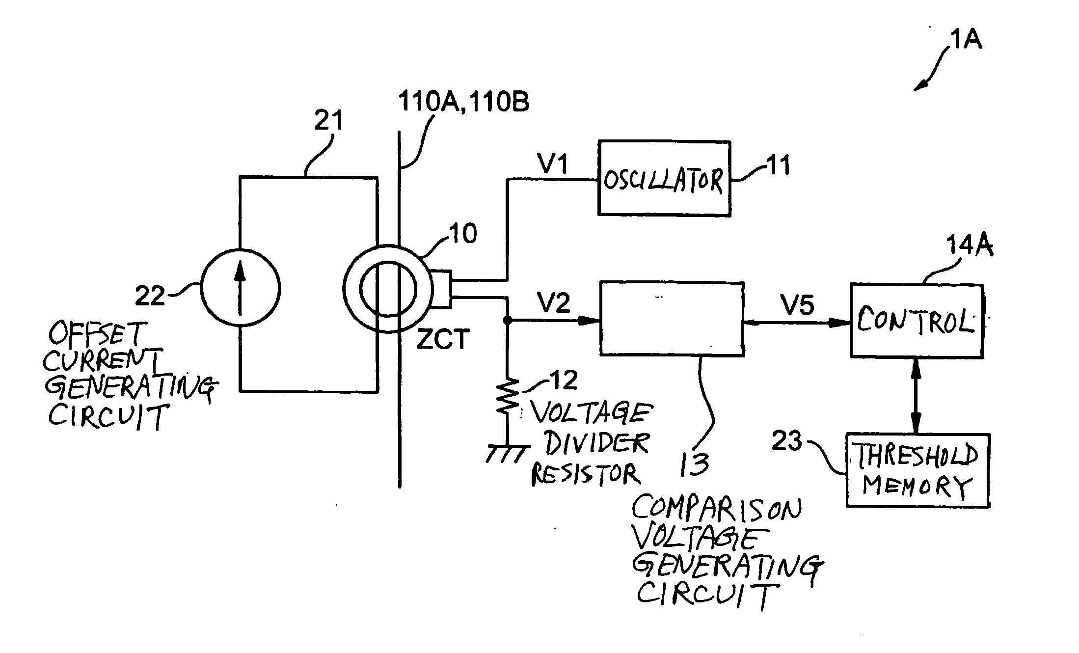
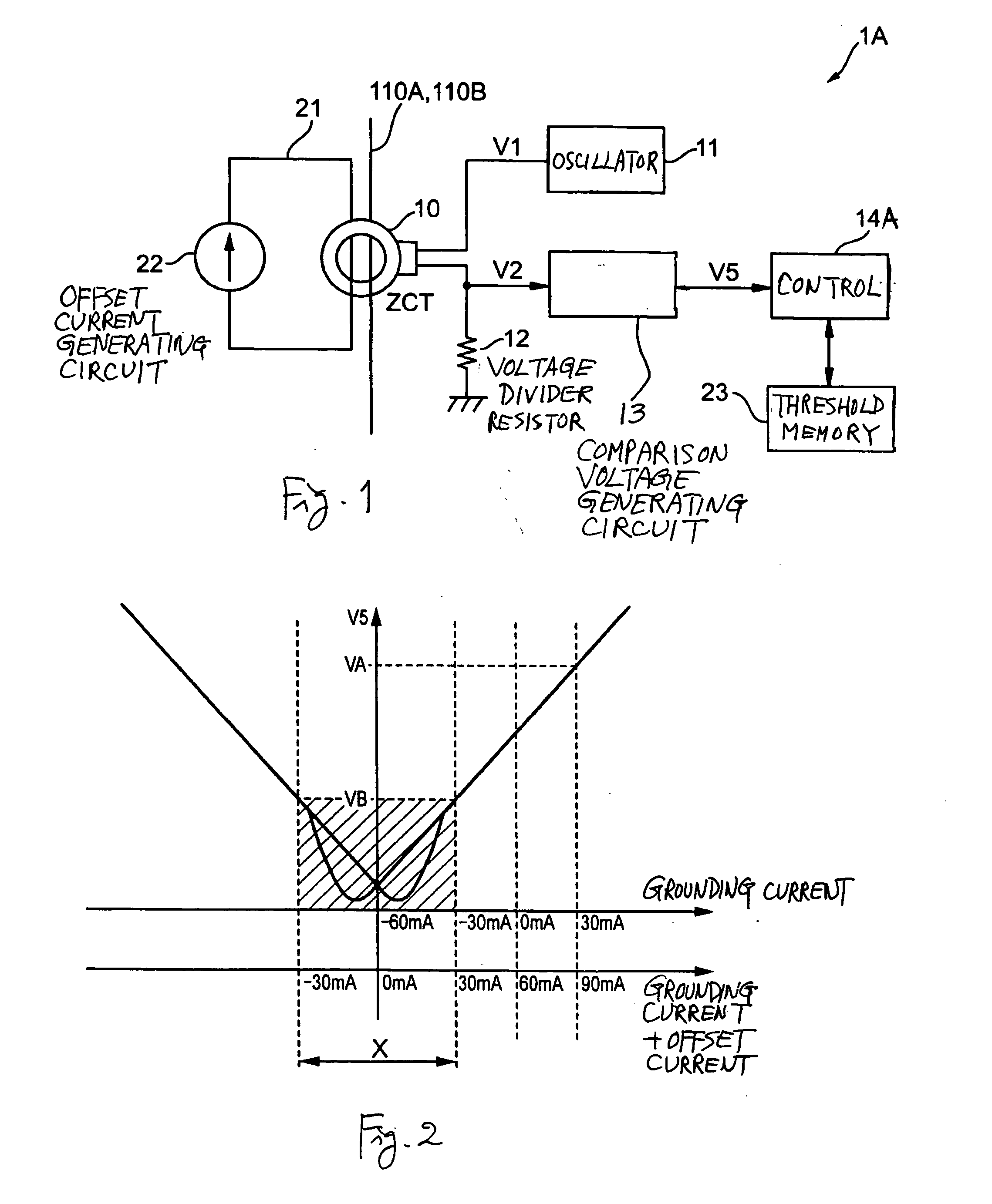
[0046] According to this first embodiment of the invention, an offset current is caused to flow through the ZCT 10 such that the minimum current range which is influenced by the hysteresis characteristic of the ZCT 10 is shifted to another range (the detectable range) where the detection of direct current value based on the comparison voltage value V5 is possible, while the upper and lower threshold values VA and VB for the judgment of presence or absence of direct grounding current relative to the source lines 110A and 110B are stored in a memory. Thus, the presence or absence of the occurrence of direct grounding current can be dependably determined without the influence of the hysteresis characteristic of the ZCT 10.

[0047] Although the first embodiment of the invention was described above by way of the direct grounding current detection circuit 1A, it goes without saying that it can be applied to a direct current detection circuit for the detection of a direct current value at th...

second embodiment

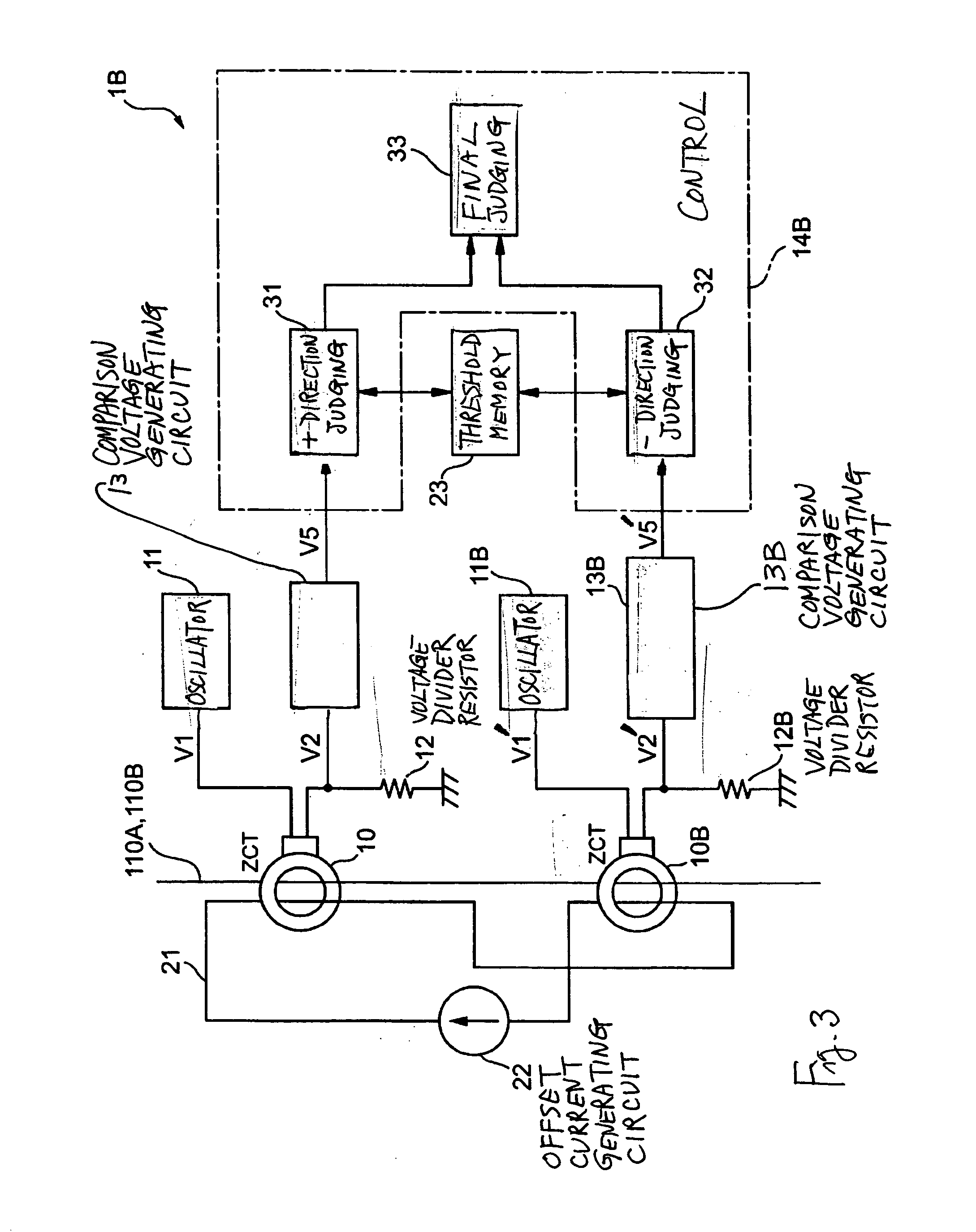
[0050]FIG. 3 is a block diagram of another direct grounding current detection circuit 1B according to this invention, adapted to be able to determine whether a direct grounding current is in the positive or negative direction although its occurrence takes place suddenly. Components which are substantially the same as those shown above in FIG. 1 are indicated by the same numerals and their structures and functions may not be described repetitiously.

[0051] The direct grounding current detection circuit 1B shown in FIG. 3 comprises not only a ZCT 10 with source lines 110A and 110B and an offset current wire 21 passing therethrough, an oscillator circuit 11, a comparison voltage generating circuit 13, an offset current generating circuit 22 and a threshold memory 23 but also another (compensatory) ZCT 10B, another (compensatory) voltage divider resistor 12B, another (compensatory) comparison voltage generating circuit 13B and a control circuit 14B. The compensatory ZCT 10B has the same ...

third embodiment

[0068]FIG. 6 is a block diagram of still another direct grounding current detection circuit 1C according to this invention, adapted to be able to determine whether a direct grounding current is in the positive or negative direction although its occurrence takes place suddenly. Components which are substantially the same as those shown above in FIG. 1 are indicated by the same numerals and their structures and functions may not be described repetitiously.

[0069] The direct grounding current detection circuit 1C shown in FIG. 6 comprises not only a ZCT 10 with source lines 110A and 110B and an offset current wire 21 passing therethrough, an oscillator circuit 11, a comparison voltage generating circuit 13 and a threshold memory 23 but also an offset current generating circuit 22C adapted to generate an offset current having different current values for each of specified periods and a control circuit 14C which concludes that a direct grounding current has occurred relative to the source...


PUM


Abstract

A direct current detection circuit has a zero-phase current transformer with source lines inserted therethrough for detecting current differences among them and generates a comparison voltage value based on a divided voltage value obtained between the zero-phase current transformer and a voltage divider resistor according to a change in the self-impedance of the zero-phase current transformer. An offset current is passed through the zero-phase current transformer to make it possible to detect on the basis of the comparison voltage value a direct current value in a range which is otherwise difficult to detect accurately on the basis of the comparison voltage value because of influence of hysteresis characteristic of the zero-phase current transformer. A control circuit detects a present direct current value based on the comparison voltage value and the value of the offset current.

Description

[0001] Priority is claimed on Japanese Patent Application 2003-290269 filed Aug. 8, 2003. BACKGROUND OF THE INVENTION [0002] This invention relates to a direct current detection circuit for detecting a direct current value by using a zero-phase current transformer (hereinafter referred to as ZCT) making use of a magnetic material like as Permalloy, such as a direct grounding current detecting circuit for detecting the occurrence of a direct grounding current used, for example, for linkage protection of a linkage apparatus. [0003] As an example of a direct grounding current detecting circuit serving as a direct current detecting circuit, Japanese Patent Publication Tokkai 11-122819 has disclosed the technology applicable to a linkage apparatus for converting direct-current power from a direct-current source into alternate-current power by using a current transformer to detect the difference between the current values flowing for the positive and negative terminals of the direct-curre...

Claims


Application Information

Patent Timeline
Patent Type & Authority Applications(United States)
IPC IPC(8): G01R31/02G01R15/18G01R19/20H01H83/02H02H3/16H02H3/347H02H3/44
CPCG01R19/20H02H3/33
Inventor TSUBOTA, YASUHIROTOYOURA, NOBUYUKIMABUCHI, MASAO
Owner ORMON CORP
Why Eureka
Try Eureka