Virtual antenna technology (VAT) and applications

Inactive Publication Date: 2005-02-10
DAVIS MUNCK P C
View PDF3 Cites 44 Cited by
  • Summary
  • Abstract
  • Description
  • Claims
  • Application Information

AI Technical Summary

Benefits of technology

To address the above-discussed deficiencies of the prior art, it is a primary object of the present invention to provide, for use in an antenna array system, derivation of the magnitude and phase of a relationship resulting from propagation delay between a sample taken at a first antenna to a sample taken at a second antenna at a different time to derive a data value for a virtual antenna. Sub-patch ant

Problems solved by technology

However, the complexity and cost of such arrays also increases rapidly as a function of the number of anten

Method used


Image

  • Virtual antenna technology (VAT) and applications
  • Virtual antenna technology (VAT) and applications
  • Virtual antenna technology (VAT) and applications

Examples


Example

FIGS. 1A through 4B, discussed below, and the various embodiments used to describe the principles of the present invention in this patent document are by way of illustration only and should not be construed in any way to limit the scope of the invention. Those skilled in the art will understand that the principles of the present invention may be implemented in any suitably arranged device.

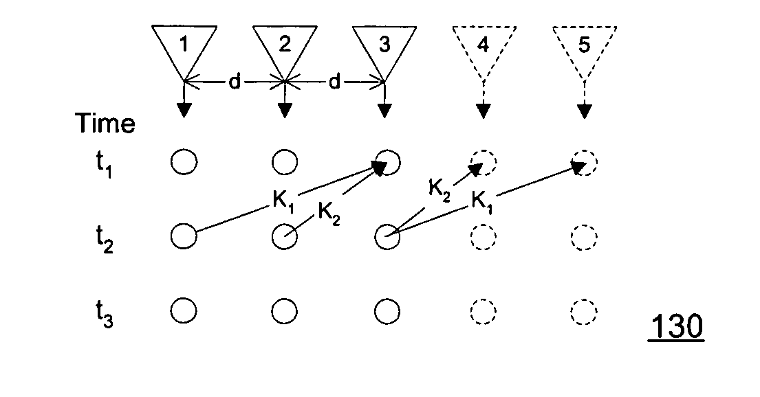
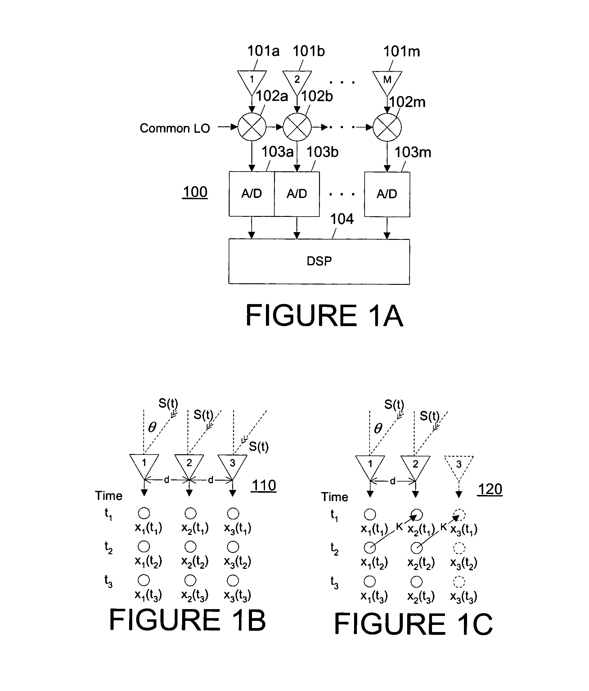
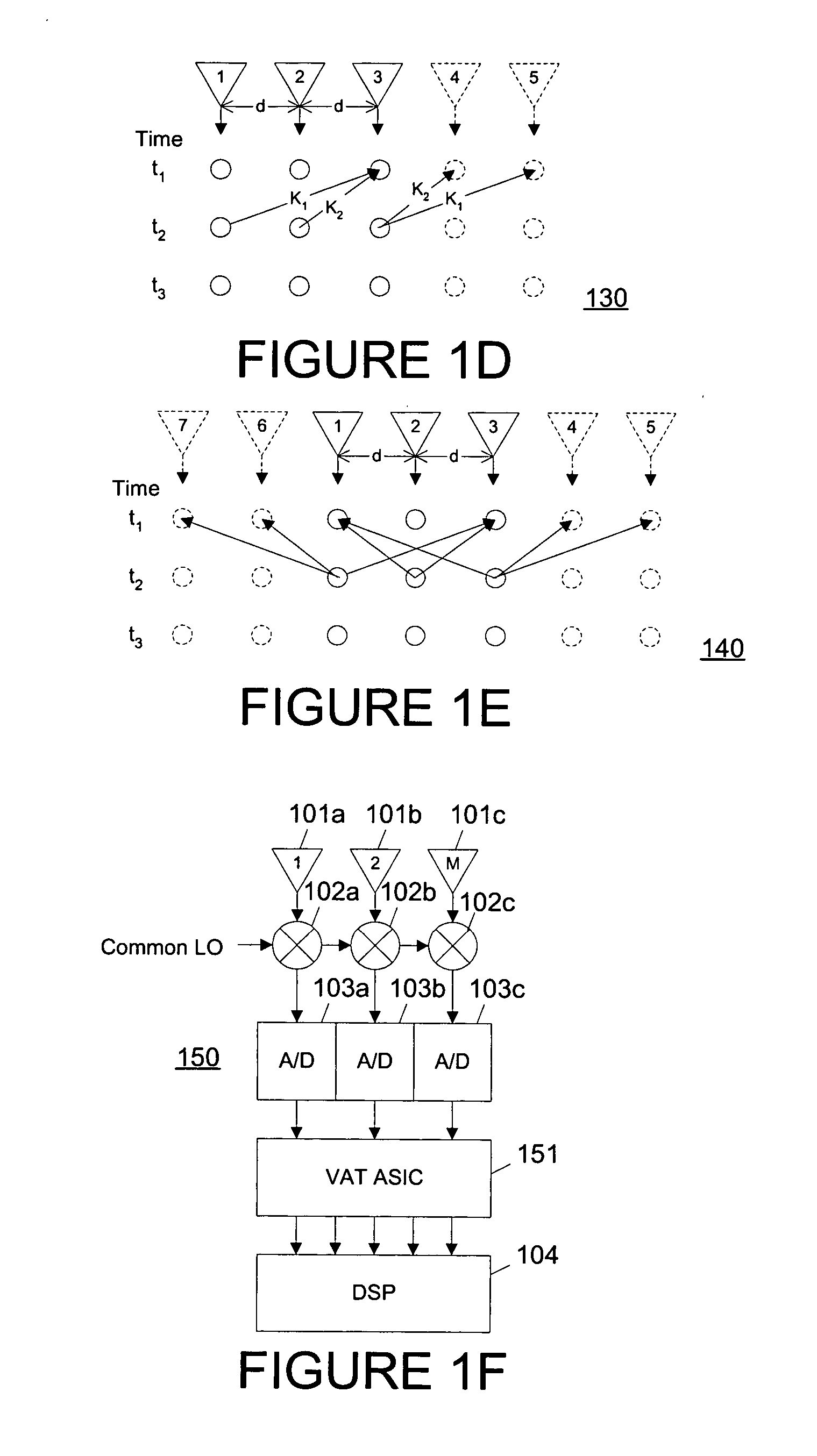
FIGS. 1A through 1F depict comparative diagrams of the structure and operation of a conventional antenna array and an antenna array with virtual antennas according to various embodiments of the present invention. FIG. 1A depicts a traditional “digital” linear antenna array system. Antenna array system 100 includes a plurality of M linearly-aligned antennas 101a-101m (where “M” and “m” are equal to each other and both equal to any positive integer greater than one). Each antenna 101a-101m receives a signal which is mixed with a common local oscillator (LO) signal at mixers 102a-102m. The outputs of...


PUM


Abstract

Within an antenna array 120, the magnitude and phase of a relationship resulting from propagation delay between a sample taken at a first antenna 1 to a sample taken at a second antenna 2 at a different time is employed to derive a data value for a virtual antenna 3. Sub-patch antennas 203 perturbed in elevation are employed to expand the elevation range of acceptable gain. Multiple arrays each providing a separate radio frequency output are employed with digital beamform steering to a single point, together with low noise amplification at the feed point, to achieve sufficient gain with an acceptable total array size. A modular implementation with fiber transport is preferably used.

Description

TECHNICAL FIELD OF THE INVENTION The present invention is directed, in general, to antenna arrays and applications and, more specifically, to an antenna array including both physical and virtual antennas as well as applications for such an antenna array. BACKGROUND OF THE INVENTION Traditional antenna arrays exhibit performance related to the number of antenna elements. However, the complexity and cost of such arrays also increases rapidly as a function of the number of antenna elements. In addition, various limitations render current antenna array technology limited in application. There is, therefore, a need in the art for improved antenna array technology, as well as improvements to various applications for antenna array technology. SUMMARY OF THE INVENTION To address the above-discussed deficiencies of the prior art, it is a primary object of the present invention to provide, for use in an antenna array system, derivation of the magnitude and phase of a relationship resultin...

Claims


Application Information

Patent Timeline
IPC IPC(8): G01S3/16H01Q
CPCH01Q21/08H01Q21/06
Inventor JUDD, MANO DORSEY
Owner DAVIS MUNCK P C
Why Eureka
Try Eureka