Relative rotational position-detection device

a technology of relative rotation and detection device, which is applied in the direction of steering linkage, instruments, transportation and packaging, etc., can solve the problems of failure and/or other problems, poor detecting resolution of conventional techniques using potentiometers, and poor electrical conta

Active Publication Date: 2007-01-11
AMITEQ
View PDF7 Cites 7 Cited by
  • Summary
  • Abstract
  • Description
  • Claims
  • Application Information

AI Technical Summary

Benefits of technology

[0005] In view of the foregoing, it is an object of the present invention to provide an improved relative-rotational-position detection apparatus which is of a type suited for precise detection based on a phase detection scheme and which can precisely detect even a minute rotational angle by permitting a sufficient gain of an output voltage level of a sensor coil.
[0007] The first magnetic body section and the second magnetic body section, which rotate in response to rotation between the first and second shafts, together form at least two ring-shaped variable magnetic coupling sections opposed to each other via a gap, and variation of magnetic coupling is different in phase between the boundary sections. Thus, there can be provided a relative rotational position detection apparatus suited to phase detection principles. Because the magnetic-coupling detecting coils can be positioned to cover the whole of the ring-shaped variable magnetic coupling boundary sections in the first and second magnetic body sections, it is possible to provide a sufficient gain of an output voltage level. As a consequence, even a minute rotational angle can be detected with high accuracy.
[0010] In an embodiment according to a first aspect of the present invention, the first and second magnetic body sections each comprise a cylindrical member having a plurality of magnetic teeth formed at unequal pitches along the circumferential direction thereof, and the plurality of magnetic teeth form groups corresponding to the plurality of boundary sections. The magnetic teeth in each of the first and second magnetic body sections differ in axial length among the groups, and the magnetic teeth of each of the groups in the first and second magnetic body sections are opposed to each other to thereby form the boundary section corresponding to the group, so that the individual boundary sections are provided in positions offset from one another in the axial direction. As a result, the present invention permits highly-accurate detection despite an extremely simple apparatus structure.

Problems solved by technology

The conventional technique of the type using a potentiometer would always suffer from poor electrical contact, failure and / or other problem since the electrical contact is implemented via a mechanical contact structure.
Further, the conventional rotational-displacement detection apparatus, known as the noncontact-type torque sensor for electric power steering employing the induction coil, is arranged to measure an analog voltage level produced in response to a minute relative rotational displacement, so that it would accomplish only a very poor detecting resolution.

Method used


Image

  • Relative rotational position-detection device
  • Relative rotational position-detection device
  • Relative rotational position-detection device

Examples


Embodiment Construction

[0032] Now, embodiments of the present invention will be described with reference to the accompanying drawings.

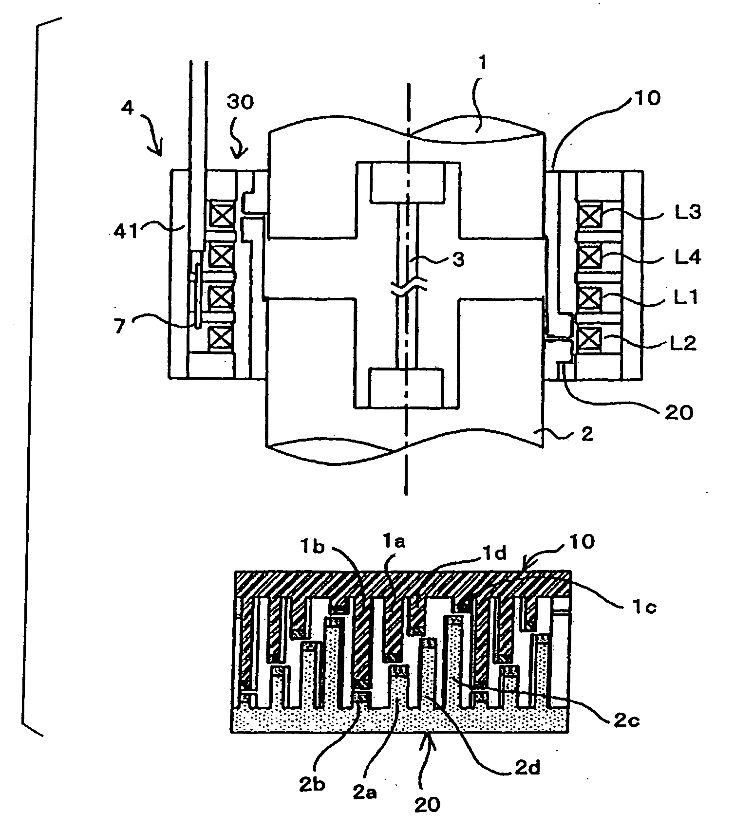
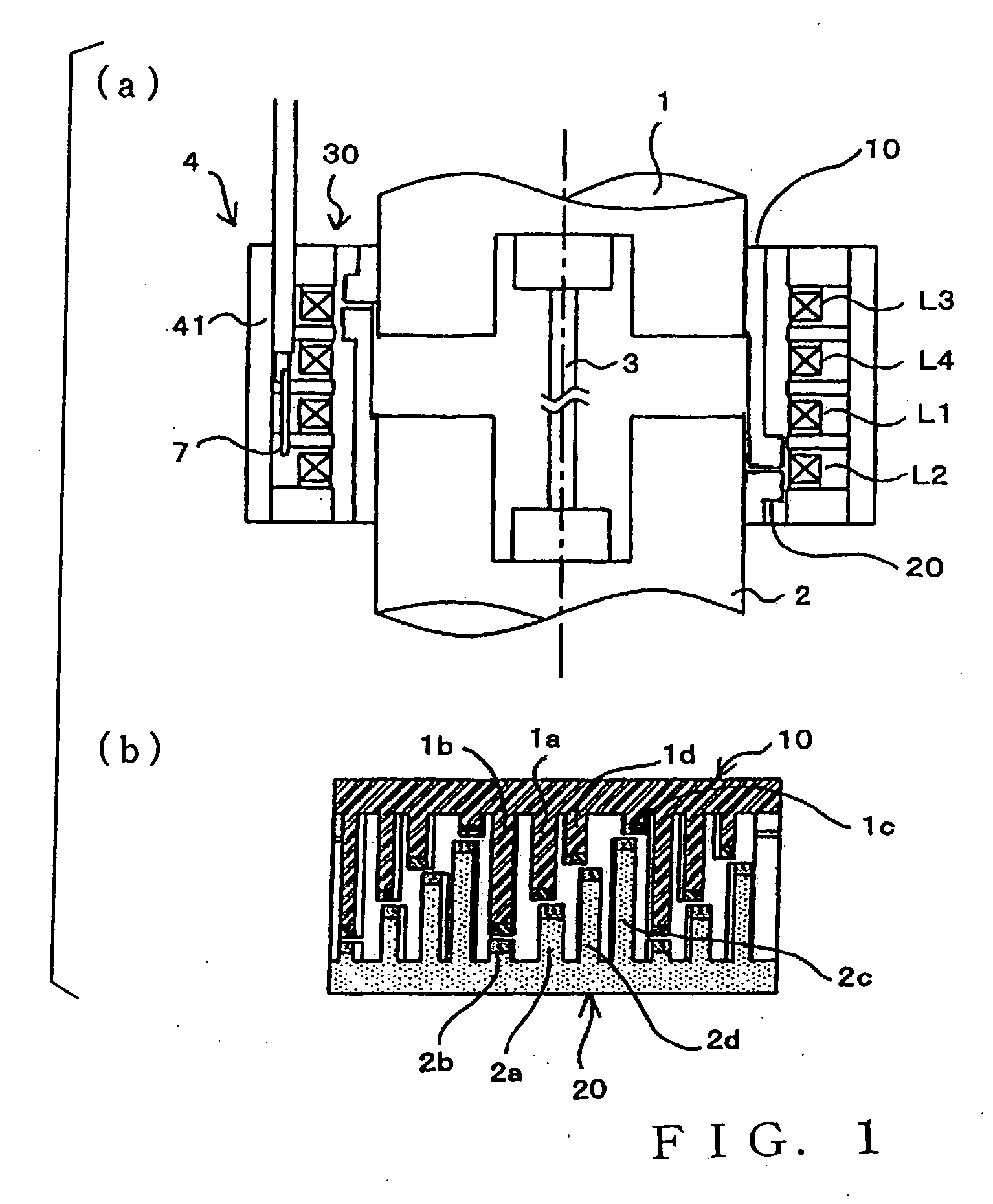
[0033]FIG. 1(a) is a partly-sectional side view schematically showing an embodiment of a relative rotational position detection apparatus in accordance with a first aspect of the present invention. The embodiment of the relative rotational position detection apparatus is constructed as a torque detection apparatus 4 for detecting torsional torque acting on a torsion bar 3 of a steering shaft connected to a steering wheel of a motor vehicle. Note that, in FIG. 1(a) and other sectional or partly-sectional schematic views in the accompanying drawings, no hatching is used to indicate sectional surfaces.

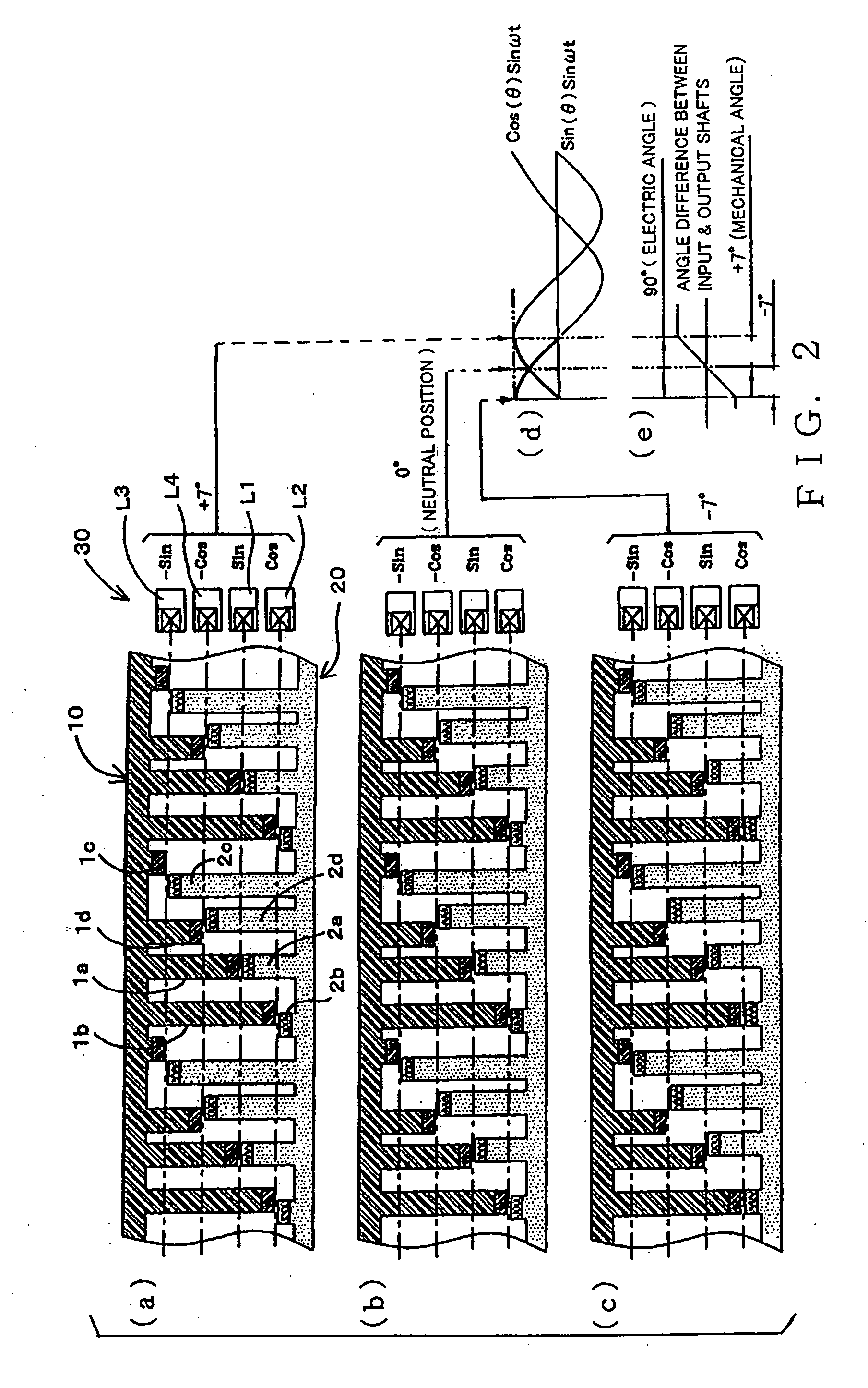
[0034] In FIG. 1(a), input and output shafts 1 and 2 are interconnected by the torsion bar 3, and these input and output shafts 1 and 2 are rotatable relative to each other through a limited angular range (e.g., from +7 degrees to −7 degrees at the most) so far as torsional def...


PUM

PropertyMeasurementUnit
electrical angleaaaaaaaaaa
rotational angleaaaaaaaaaa
magneticaaaaaaaaaa

Abstract

First and second shafts (1, 2) are interconnected via a torsion bar (3) for torsional (or rotational) movement relative to each other, and first and second magnetic body sections (10, 20) are provided to rotate in interlocked relation to the rotation of the first and second shafts, respectively. The first and second magnetic body sections form at least two ring-shaped variable magnetic coupling sections opposed to each other via a gap, magnetic coupling in each of the boundary sections varies in response to variation of a relative rotational position between the first and second shafts, and variation of the magnetic coupling differs in phase between the boundary sections. Coil section (30) includes magnetic-coupling detecting coils (L1-L4) provided in corresponding relation to the boundary sections. Each of the first and second magnetic body sections is of a cylindrical shape and has a plurality of magnetic teeth formed at unequal pitches along the circumferential direction thereof, and the magnetic teeth differ in axial length among tooth groups corresponding to the boundary sections.

Description

TECHNICAL FIELD [0001] The present invention relates to an improved apparatus for detecting a relative rotational position between two shafts, which is suitable for use as, for example, a torque sensor for detecting a torsional load applied to a power steering shaft of a motor vehicle. BACKGROUND ART [0002] Of various types of techniques for detecting torsional amounts of two relatively-rotatable shafts, there have been well known those which are characterized by provision of detection devices, such as a potentiometer or resolver devices, on input and output shafts interconnected via a torsion bar. According to the above-mentioned technique using a potentiometer, a slider is mounted on the input shaft while a resistor is mounted on the output shaft, so that a position of the slider contacting the resistor varies in accordance with variation in a relative rotational position between the input and output shafts to thereby provide an analog voltage corresponding to the relative rotatio...

Claims


Application Information

Patent Timeline
Patent Type & Authority Applications(United States)
IPC IPC(8): G01B7/14B62D6/10G01L3/10
CPCB62D6/10G01L3/109G01L3/101G01L3/104G01L3/105
Inventor GOTO, ATSUTOSHISAKAMOTO, KAZUYASAKAMOTO, HIROSHI
Owner AMITEQ
Why Eureka
Try Eureka