Meander-lineless wide bandwidth l-shaped slot line antenna

a slot line, wide bandwidth technology, applied in the direction of antenna supports/mountings, resonant antennas, antenna earthings, etc., can solve the problems of reducing the overall size of the antenna

Inactive Publication Date: 2005-09-22
BAE SYST INFORMATION & ELECTRONICS SYST INTERGRATION INC
View PDF11 Cites 8 Cited by
  • Summary
  • Abstract
  • Description
  • Claims
  • Application Information

AI Technical Summary

Benefits of technology

[0022] In the case of ultra-wideband service, the band from 3 GHz to 9 GHz is easily accommodated by this asymmetric, meander-lineless, shorted and capacitively-shunted L-shaped slot line antenna.
[0023] The result is that the miniature size of the antenna can be m

Problems solved by technology

As with all meander line loaded antennas, a significant cost to the antenna is the provision of the meander line itself, which requires spaced-apart plates or strips which provide for an impedance discontinuity that in effect lengthens the overall size of the antenna while at the same time keeping the antenna small due to the folded meander line configuration.
The separate fabrication of the meander line not only complicates construction of the antenna but also is somewhat costly to manufacture.
However, such stacking of patch antennas is problematic because the antennas interfe

Method used


Image

  • Meander-lineless wide bandwidth l-shaped slot line antenna
  • Meander-lineless wide bandwidth l-shaped slot line antenna
  • Meander-lineless wide bandwidth l-shaped slot line antenna

Examples


Embodiment Construction

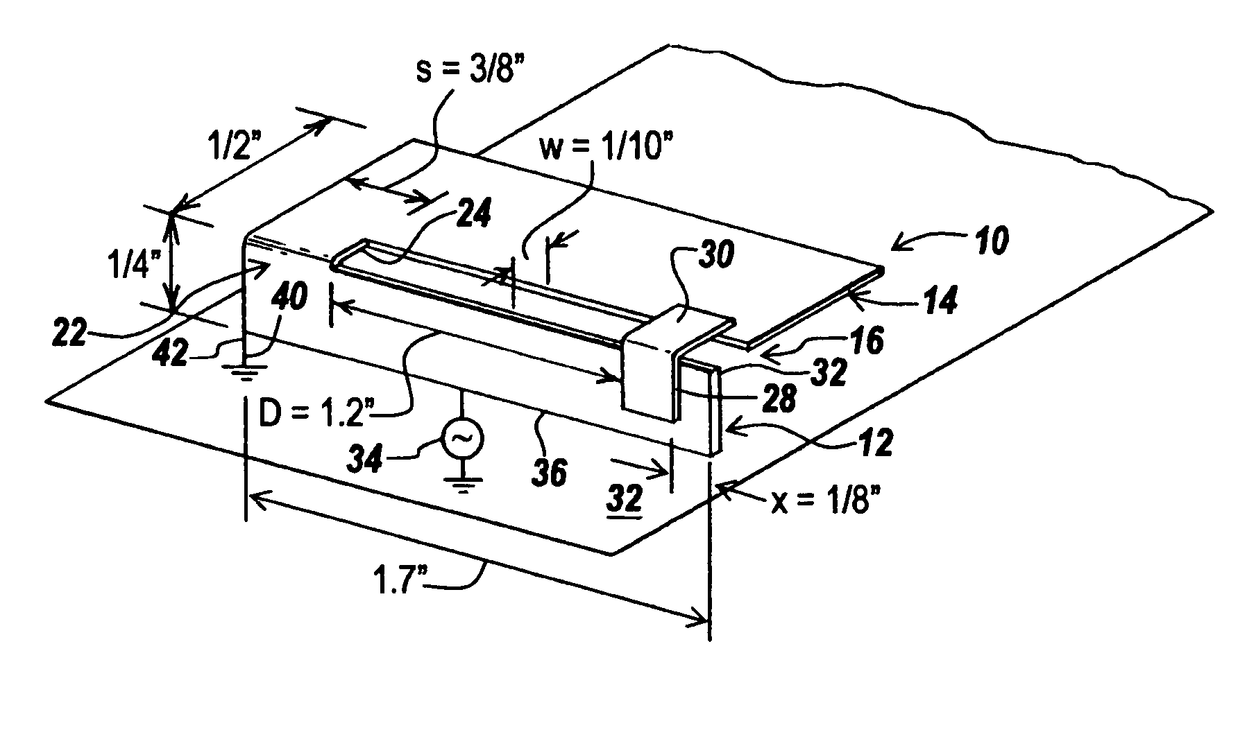
[0035] Referring now to FIG. 1, an asymmetric L-shaped slot line antenna 10 is comprised of a vertically extending plate 12 meeting a horizontally extending plate 14 at a slot 16 which is formed by edges 18 and 20 of plates 12 and 14.

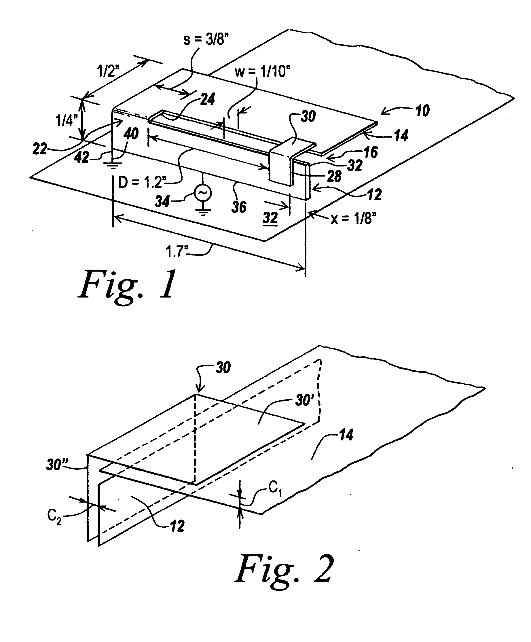
[0036] Slot 16 is shorted at 22 which bridges slot 16 a distance S from edge 24 of plate 14. The width of slot 16 is designated W, whereas the distance from edge 24 of short 22 to edge 26 of L-shaped capacitive member 30 is designated D. It is noted that right-hand edge 28 of capacitive element 30 is spaced a distance X= 1 / 8 inch from edge 32 of upstanding plate 12.

[0037] The asymmetric slot line antenna structure 10 is positioned above a ground plane 32 and is driven by signal source 34 between ground plane 32 and edge 36 of vertical plate 12.

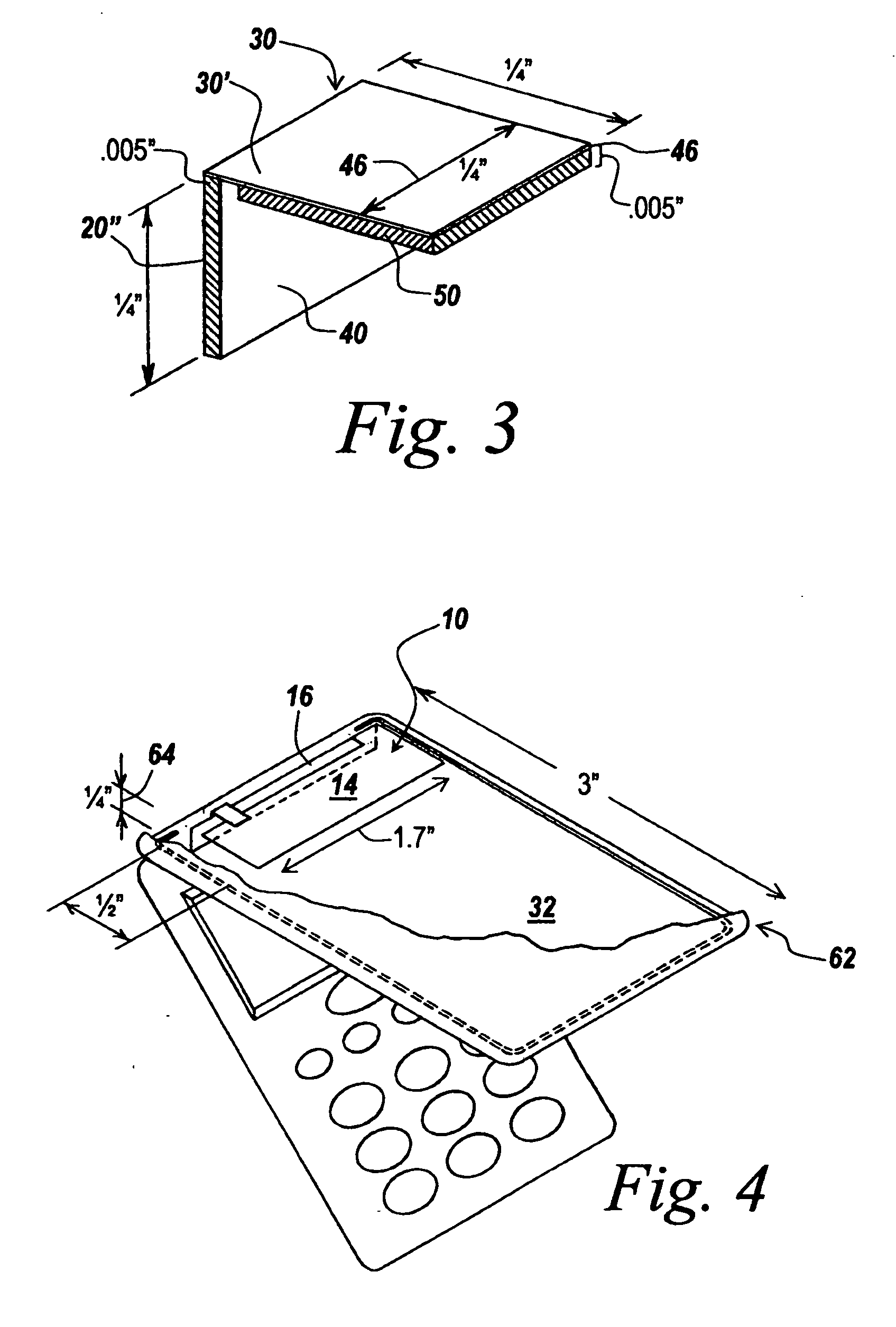
[0038] In one embodiment especially useful for the cellar and PCS applications, the length of horizontally extending plate 14 is 1 / 2 inch, whereas the width of plate 14 is 1.7 inches to match the width of verti...


PUM


Abstract

An asymmetric slotted L-shaped antenna is provided with a wide bandwidth in an exceedingly small size with good gain across the entire bandwidth by shorting out one end of the slot and by providing a capacitor at the other end of the slot, with the result that with appropriate capacitance, spacings and dimensions, the impedance of the slotted transmission line cancels the reactance of the antenna such that the gain of the antenna can be made to match a similar sized meander line loaded antenna.

Description

FIELD OF THE INVENTION [0001] This invention relates to miniaturized broad bandwidth antennas and more particularly to an asymmetric slotted L-shaped antenna having a shorting stub at one end of the slot and a capacitor shunting the other end of the slot. BACKGROUND OF THE INVENTION [0002] Meander line loaded antennas are known and are exemplified by U.S. Pat. Nos. 5,790,080; 6,313,716; 6,323,814; 6,373,440; 6,373,446; 6,480,158; 6,492,953; 6,404,391 and 6,590,543. These patents are assigned to the assignee hereof and are included herein by reference. [0003] In all of the prior meander line loaded antennas there is a right angle between the horizontal and vertical radiators, with the top plate being parallel to the ground plane plate utilized. This plate configuration optimizes the current distribution for maximum bandwidth. [0004] As illustrated in the above patents, in order to make reduced-sized or miniaturized antennas, a meander line has been utilized to load the antenna in suc...

Claims


Application Information

Patent Timeline
IPC IPC(8): H01Q1/24H01Q9/04H01Q13/10
CPCH01Q1/243H01Q9/0442H01Q9/0421
Inventor APOSTOLOS, JOHN T.
Owner BAE SYST INFORMATION & ELECTRONICS SYST INTERGRATION INC
Why Eureka
Try Eureka