
Electronic pen, and control device and method thereof

a technology of electronic pens and control devices, applied in the field of electronic pens, can solve the problems of difficult production, difficult repair and maintenance, and difficult assembly of the pen arrangement, and achieve the effect of convenient mounting and maintenan

Active Publication Date: 2005-02-10
ANOTO AB
View PDF17 Cites 78 Cited by
  • Summary
  • Abstract
  • Description
  • Claims
  • Application Information

AI Technical Summary

Benefits of technology

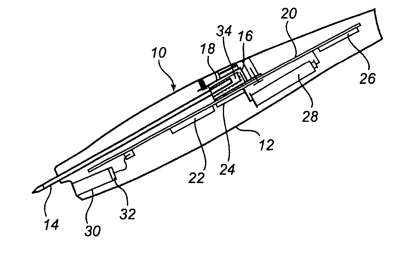
[0012] Thus an object of the present invention is to provide an electronic pen with a force sensor arrangement which is easy to mount and maintain.
[0013] It is also an object to provide such a pen whose force sensor arrangement is both reliable and durable.
[0014] A further object is to provide an electronic pen with a force sensor arrangement whose characteristics can be customised without radical changes of the construction of the arrangement.

Problems solved by technology

A pen of the above construction, however, suffers from several drawbacks.
The sensor arrangement of the pen is relatively complicated to assemble, which makes production as well as repair and maintenance difficult and expensive.
Moreover the sensor arrangement of the pen will probably have a limited life by the point of the application element being quite heavily worn when cooperating with the guide hole in the electrode plate.
A further drawback is that the characteristics of the sensor arrangement, i.e. its functional relationship between application force and output signal, can only be modified within narrow limits and then by way of radical construction changes of the sensor arrangement.

Method used


Image

  • Electronic pen, and control device and method thereof
  • Electronic pen, and control device and method thereof
  • Electronic pen, and control device and method thereof

Examples


second embodiment

[0093] In the second embodiment, the size of the measuring signal is instead controlled in relation to the voltage range Vmin-Vmax of the AD converter by the constant current source being caused by a control unit to draw a predetermined current through the force sensor. The predetermined current is fixed to give, within a predetermined force range, measuring signals which with the desired resolution are mapped against the voltage range Vmin-Vmax of the AD converter. It will be appreciated that the above problems are thus overcome without noise being amplified relative to the measuring signal. The thus controlled analog measuring signal is illustrated in FIG. 8 where the conversion range is limited by a high and a low switch point Vhigh and Vlow respectively. These switch points can, but do not have to, coincide with the voltage levels that define the measuring range Vmin-Vmax. Each time the analog measuring signal reaches the low or the high switch point Vlow, Vhigh, the constant cu...

first embodiment

[0095] It should also be pointed out that the above hysteresis can also be introduced in the first embodiment involving controlling of the voltage range of the AD converter.

[0096] The resulting, digitised measuring signal is then issued with an indication of the associated conversion range. The receiver of the digitised measuring signal conveniently has access to the conversion data that indicates the size of each conversion range, and also calibration data corresponding to a parametrisation of the relationship between resistance and force of the force sensor. The relationship can be specific for a given force sensor, or an average relationship.

[0097] It should be pointed out that all of the circuit solutions that have been described above are generally applicable to electronic pens and can cooperate with any form of force sensor that can be caused to emit an analog measuring signal corresponding to the force applied to the pen stem of the pen. Such force sensors can be based on, f...


PUM


Abstract

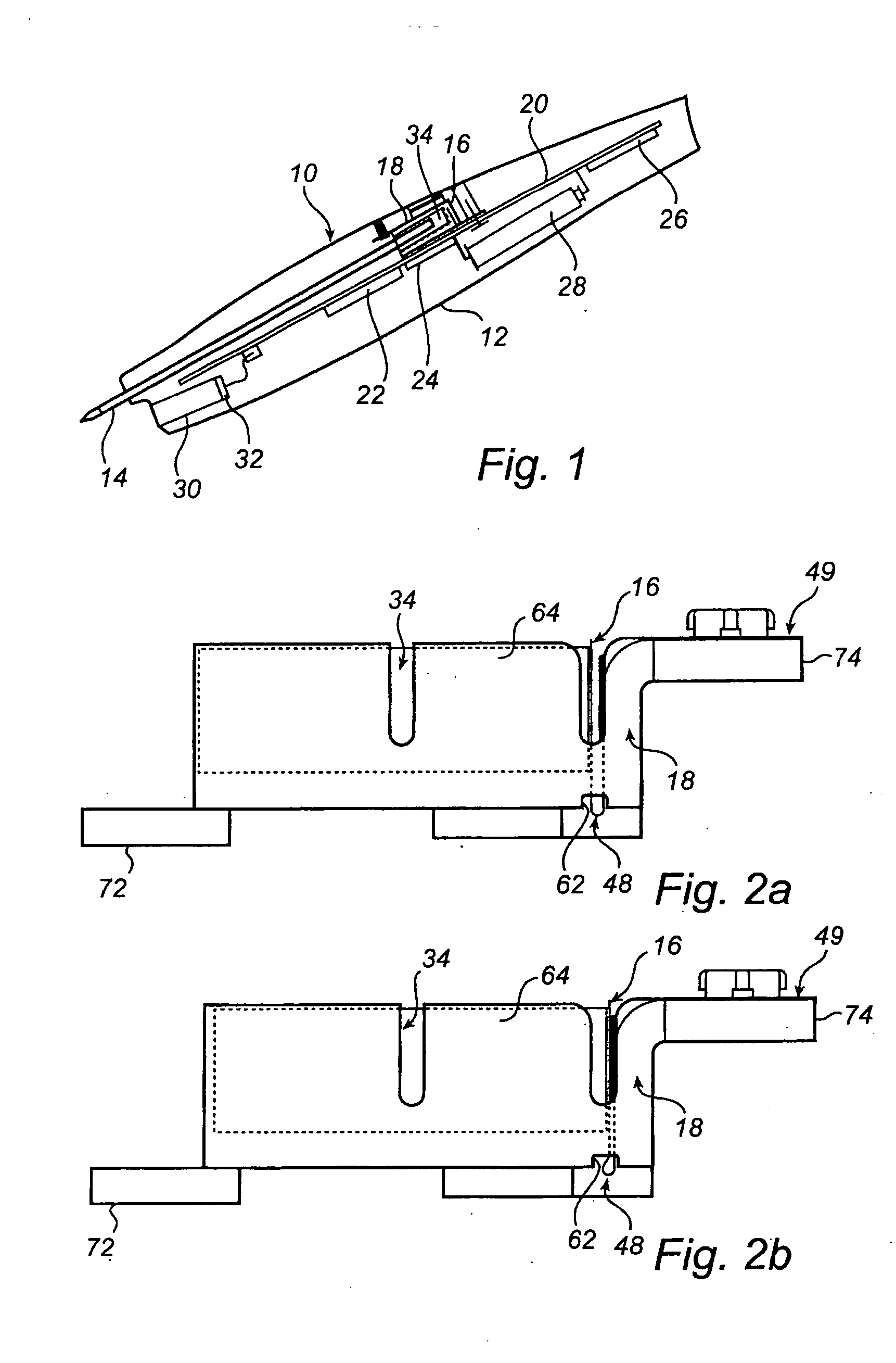
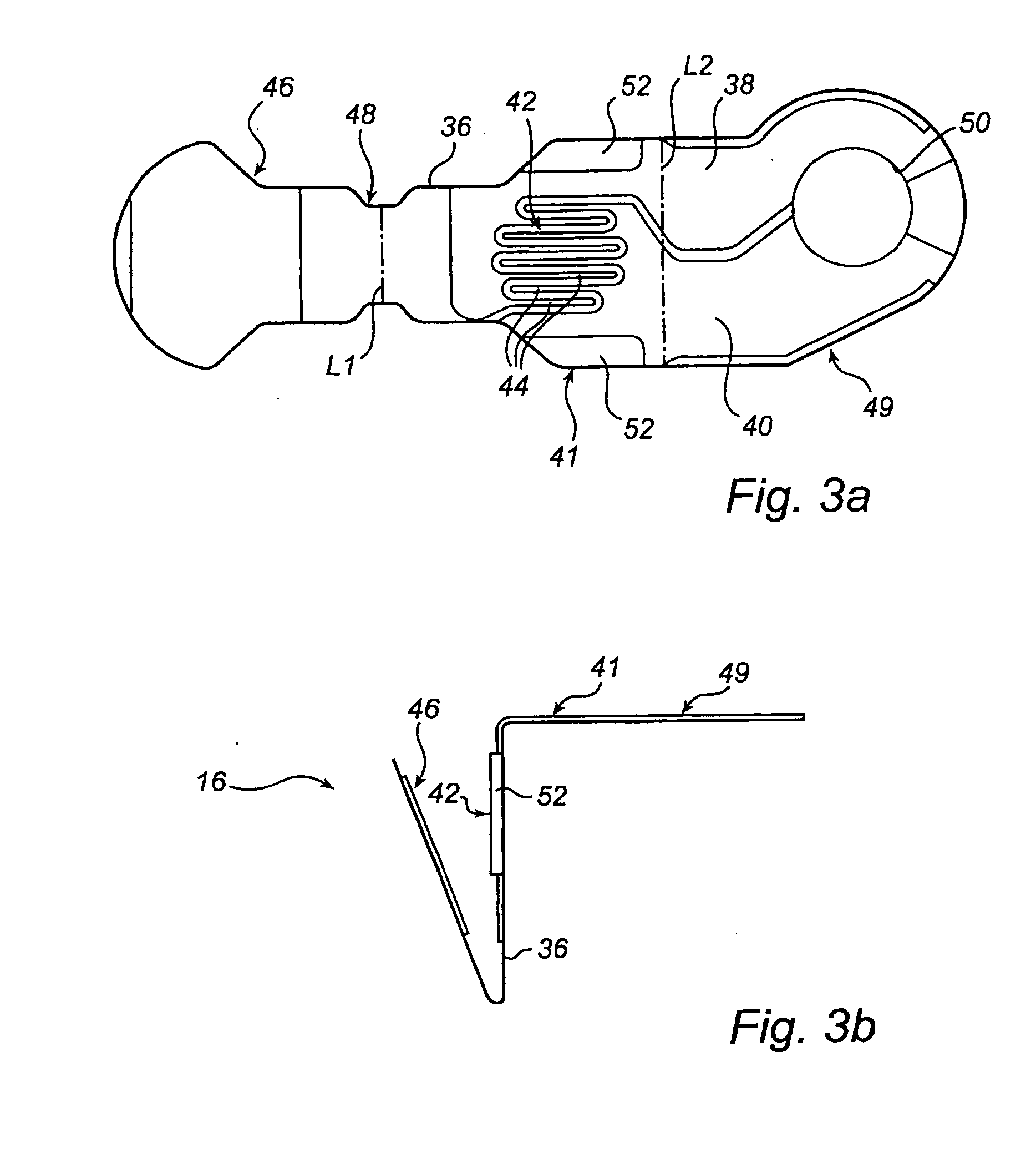
An electronic pen (10) has a force sensor (16) whose electrical resistance varies in accordance with the amount of force applied to the pen stem (14) of the pen. The force sensor (16) is a modular unit with an electrode and a closure, which are mutually arranged in an essentially electrically insulated initial position. The closure, which conveniently is cantilevered on the electrode, is adapted to receive axial forces from the pen stem (14) and thereby to be urged to an activated position in electrical contact with the electrode. The closure is also arranged, on relaxation of the axial forces, to automatically spring from the activated position back to the initial position. A control device is used in a method for controlling the pen based on an analog measuring signal from the force sensor (16) by a processor (22) comparing the analog measuring signal with a fixed reference signal and, based on the comparison, selectively initiating conversion of the analog measuring signal into a sequence of digital force values.

Description

FIELD OF THE INVENTION [0001] The present invention relates generally to electronic pens for recording of handwritten information. BACKGROUND ART [0002] Electronic pens have been developed as a complement to keyboards and mice for controlling computer-based systems and inputting information to them. Such a pen is associated with an internal and / or external position detector which electronically records the pattern of movements of the pen over a base and generates an electronic copy thereof, below referred to as electronic handwriting. [0003] The position detector can be based on, for instance, recording of a position-coding pattern on the base, mechanical detection of movements, use of accelerometers and / or gyroscopes, triangulation of electromagnetic or acoustic signals, pressure detection in the base, recording of changes in an electromagnetic field, or a combination of such techniques. [0004] In many electronic pens, the position detector is activated based on an output signal fr...

Claims


Application Information

Patent Timeline
Patent Type & Authority Applications(United States)
IPC IPC(8): G06F3/0354
CPCG06F3/03545
Inventor BURSTROM, STEFANBRYBORN, MATTIASGREDINGER, PETERSTROMBERG, OLAHORRDIN, MAGNUS
Owner ANOTO AB
Learn More