

Variable optical-property element
a variable optical and element technology, applied in the field of variable optical property elements, can solve the problem that little is known about the construction of a conventional variable optical property elemen
- Summary
- Abstract
- Description
- Claims
- Application Information
AI Technical Summary
Benefits of technology
Problems solved by technology
Method used
Image

Examples
Embodiment Construction
In accordance with the embodiments shown in the drawings, the present invention will be described below.
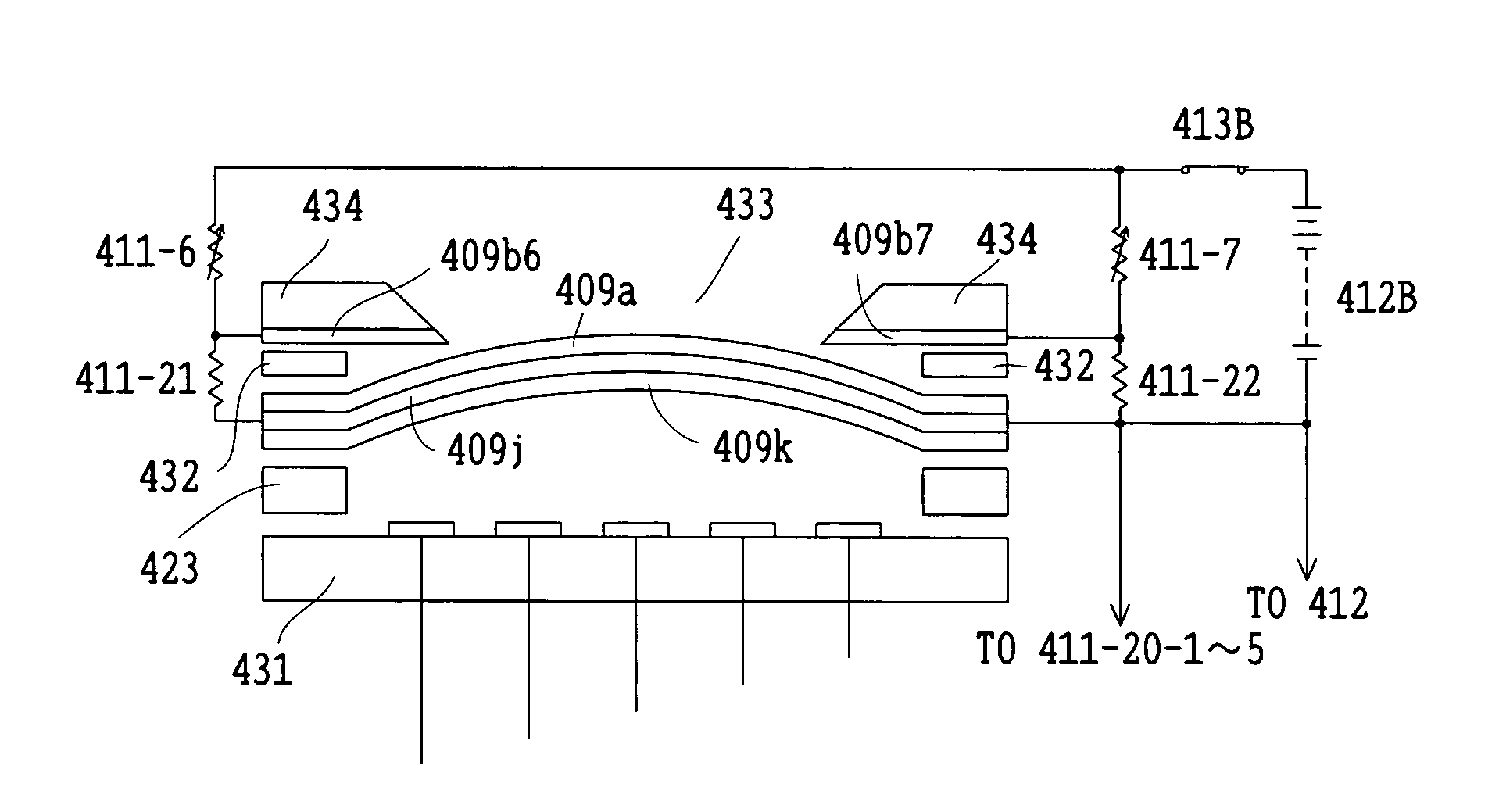
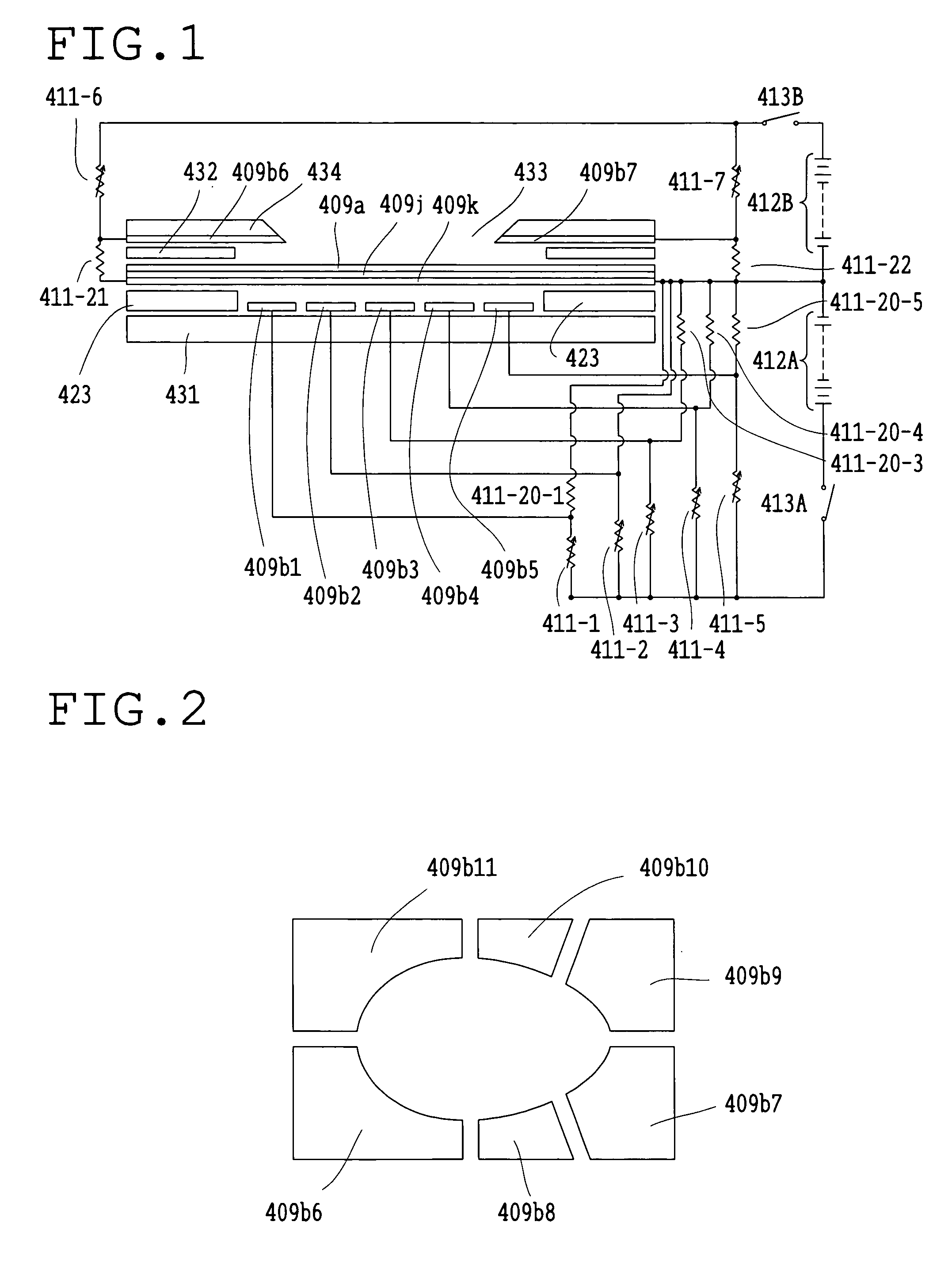
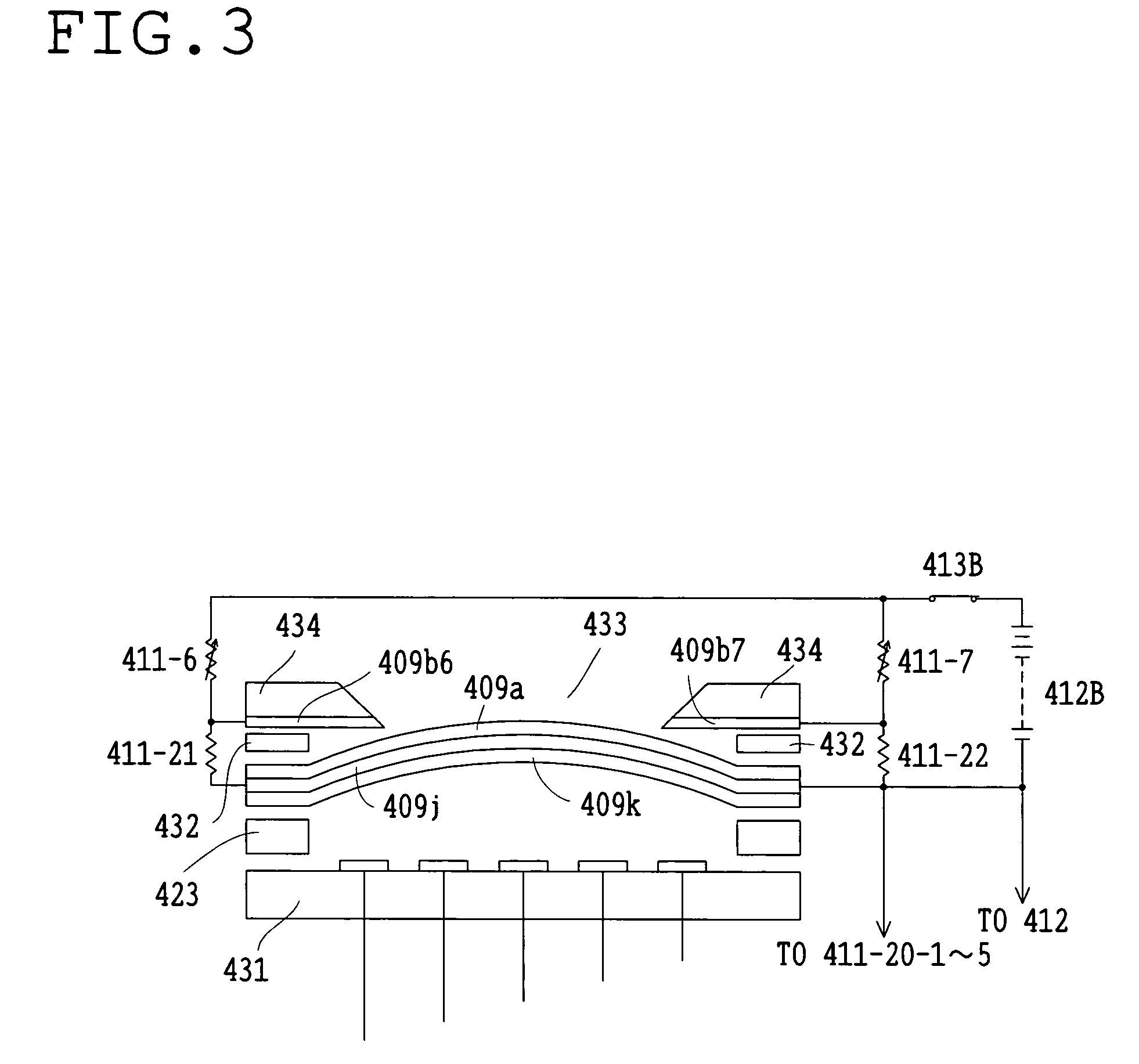
FIG. 1 shows one embodiment of the variable optical-property element according to the present invention.
This embodiment is constructed as an electrostatically-driven deformable mirror which can be deformed into both the concave and convex shapes. In this deformable mirror, a thin film 409a formed as the reflecting surface (the optical surface), a deformable substrate 409j, and a deformable electrode plate 409k are laminated and the periphery of the mirror is mounted on a lower substrate 431 through a supporting base 423. Between the lower substrate 431 and the electrode plate 409k, fixed electrodes 409b1, 409b2, 409b3, 409b4, and 409b5 are arranged on the lower substrate 431. On the thin film 409a, a holding frame 432 opposite to the supporting base 423, fixed electrodes 409b6 and 409b7, and an upper substrate 434 are laminated at the periphery. An opening 433 for incidence an...
PUM
| Property | Measurement | Unit |
|---|---|---|
| distance | aaaaa | aaaaa |
| optical-property | aaaaa | aaaaa |
| electric force | aaaaa | aaaaa |
Abstract
Description
Claims
Application Information