
Arrangement and use of a slit diaphragm

a diaphragm and slit technology, applied in the direction of instruments, radiation pyrometry, material analysis, etc., can solve the problems of high cost, complex structure of devices, and inability to continuously adjust the slit width, etc., to achieve the effect of achieving objects, and achieving objects is also costly, and the cost of manufacturing is high

Inactive Publication Date: 2005-02-10
TECAN TRADING AG
View PDF8 Cites 6 Cited by
  • Summary
  • Abstract
  • Description
  • Claims
  • Application Information

AI Technical Summary

Benefits of technology

The present invention provides a device and method for adjusting the slit height and width of a slit diaphragm used in optical measurements. The device has a motor drive with a perpendicular axis of rotation, which simplifies the mechanism and reduces manufacturing costs. The slit width can be adjusted using two slides moved linearly at least partially symmetrically to each other, resulting in a desired slit through at least partial overlap of optical openings. The slit height and width can be changed practically continuously, even during the irradiation of a sample. The slit width can also be automatically or tailored to a specific sample behavior, in accordance with preset parameters. The technical effects of the invention include a simpler mechanism, cost-effectiveness, and continuous adjustability of the slit width and height.

Problems solved by technology

However, it has the disadvantage that a costly and complex mechanism must be provided for changing the slit width.
This achievement of the object is also costly and does not allow continuous adjustment of the slit width.
This device has a very complex construction and is accordingly costly to manufacture.

Method used


Image

  • Arrangement and use of a slit diaphragm
  • Arrangement and use of a slit diaphragm
  • Arrangement and use of a slit diaphragm

Examples


first embodiment

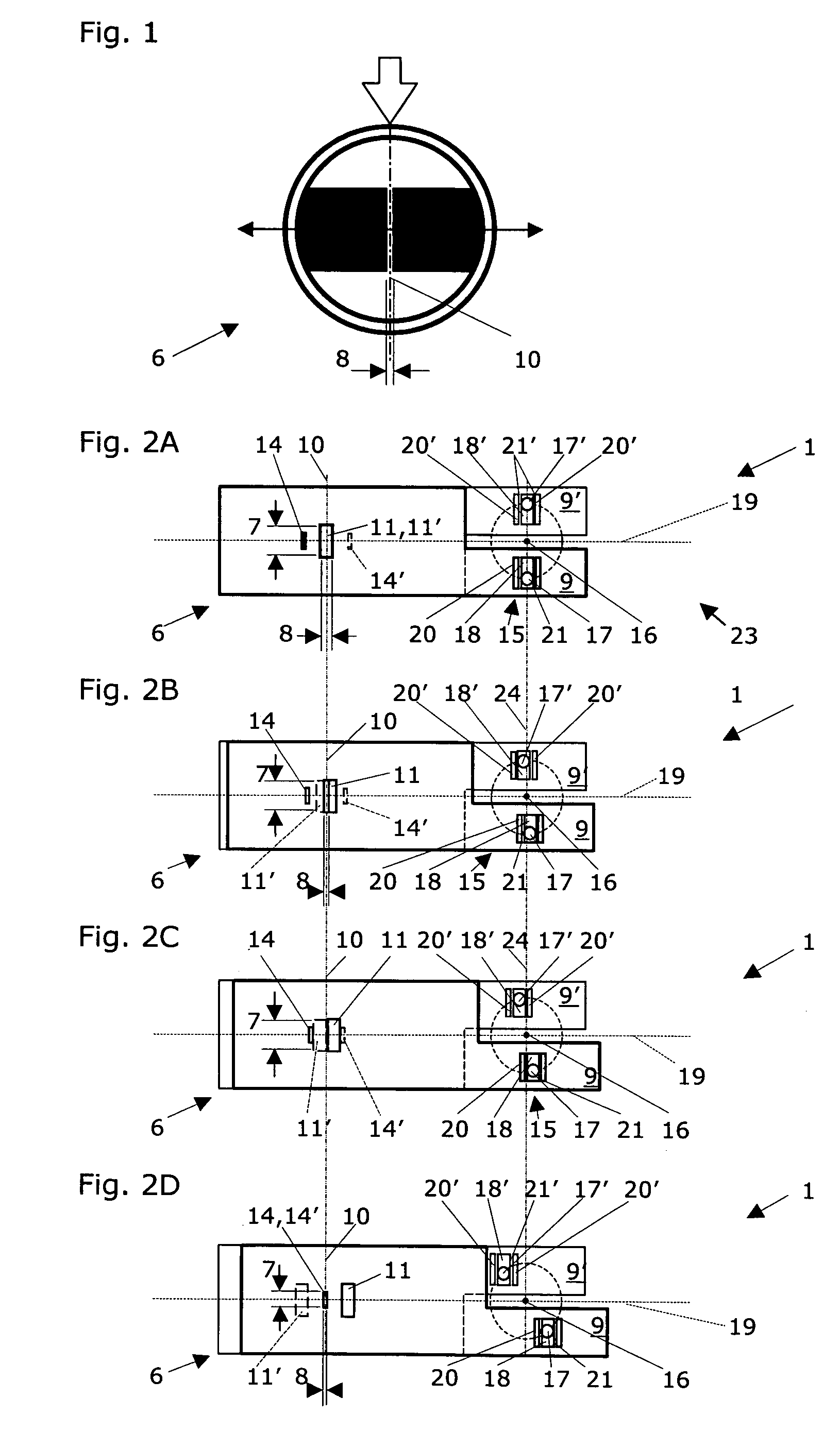
[0028]FIG. 2 shows a front view of a slit diaphragm according to the present invention in a first embodiment, having two slides positioned on two separate parallel lines for varying the slit width or the slit height. A device 1 is shown for delimiting a field 3 impinged by light from a light source 2 (cf. FIG. 5), particularly on the surface of an optical element 4 and / or a sample 5. Optical elements 4 include all typical optical components, such as gratings, mirrors, fiber-optic cables, lenses, and the like. Samples 5 include fluids, such as solutions, suspensions, and liquid-gas mixtures, as well as solids, such as emulsions, tissue sections, and cell cultures. The device 1 includes a slit diaphragm 6 having a slit height 7 and a slit width 8, the slit width 8 and / or the slit height 7 being continuously adjustable. The device 1 according to the present invention is distinguished in that the slit diaphragm 6 has first and second linearly movable sliders 9, 9′, positioned parallel t...

second embodiment

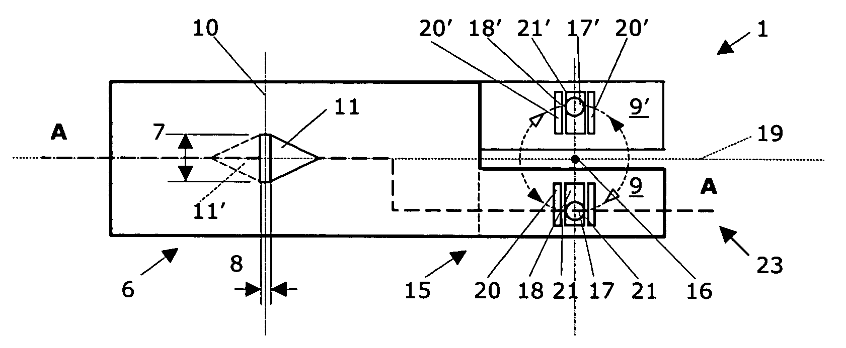
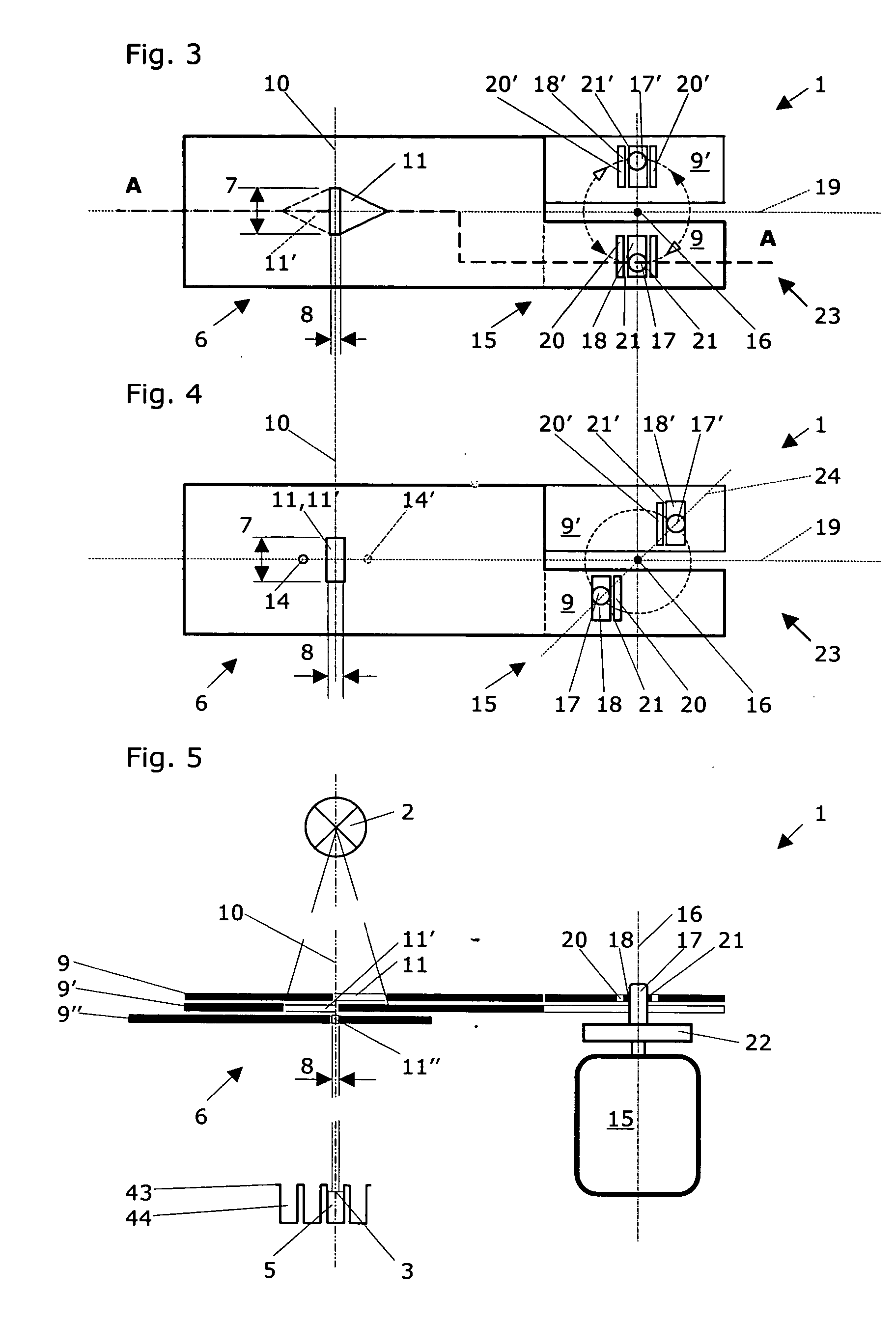
[0037]FIG. 3 shows a front view of a slit diaphragm according to the present invention in a second embodiment, having two slides positioned on two separate parallel lines for varying the slit width and / or slit height, in a first slide position, in which the two slides are essentially congruent to one another and define a specific slit width and a maximum slit height. The optical openings 11, 11′ in the two slides 9, 9′ have a pentagonal shape and are mirror-symmetric to one another here. Through a slight rotation of the rotating disk 22 using the motor drive 15 in the counterclockwise direction (solid arrow tip) around the center of rotation 16, the slides 9, 9′ are moved toward one another in such a way that the slit height 7 remains unchanged, but the slit width 8 is reduced (similarly to FIG. 2). By rotating the rotating disk 22 using the motor drive 15 counterclockwise (empty arrow tip) around the center of rotation 16, the slides 9, 9′ are moved toward one another in such a way...

fourth embodiment

[0038] If this increase of the slit width 8 is not desired—according to the slit diaphragm according to the present invention—a third slide 9″, positioned on a further separate, parallel line, having a narrow optical opening 11″ which defines a fixed slit width 8, may be positioned symmetrically to the optical axis in such a way (cf. FIG. 5) that with increasing movement of the rotating disk 22 clockwise, the slit height 7 may be varied while the slit width now remains the same.


PUM

PropertyMeasurementUnit
angleaaaaaaaaaa
angleaaaaaaaaaa
heightaaaaaaaaaa

Abstract

Device (1) and method for delimiting a field (3) impinged with light from a light source (2), particularly on the surface of an optical element (4) and / or sample (5), having a slit diaphragm (6) including a slit height (7) and a slit width (8), which includes first and second linearly movable slides (9, 9′), positioned parallel to one another on two separate parallel lines, which are movable at least partially symmetrically to one another in relation to an optical axis (10), each of the two slides (9, 9′) including at least one optical opening (11, 11′), which—for continuous adjustment of at least the slit height (7) or the slit width (8)—may be positioned at least partially on the optical opening (11′, 11) of the neighboring slide (9′, 9) in the region of the optical axis (10). The device (1) according to the present invention and the method according to the present invention are distinguished in that the device (1) includes a motor drive (15) having an axis of rotation (16) for moving the two slides (9, 9′) in a movement direction (19), this axis of rotation (16) of the motor drive (15) being positioned perpendicularly to this movement direction (19).

Description

CROSS-REFERENCE TO RELATED APPLICATIONS [0001] This application claims priority of the Swiss patent application No. CH 1230 / 03 filed on Jul. 14, 2003. TECHNICAL FIELD OF THE INVENTION [0002] The present invention relates to a device according to the preamble of independent claim 1 for delimiting a field impinged with light from a light source, particularly on the surface of an optical element and / or sample, having a slit diaphragm including a slit height and a slit width, which includes first and second linearly movable slides positioned parallel to one another on two separate parallel lines, which are movable at least partially symmetrically to one another in relation to an optical axis, each of the two slides including at least one optical opening which may be positioned at least partially on the optical opening of the neighboring slide in the region of the optical axis for continuous adjustment of at least the slit height or the slit width. In addition, the present invention rela...

Claims


Application Information

Patent Timeline
Patent Type & Authority Applications(United States)
IPC IPC(8): G01J3/04G01N21/25G01N21/64
CPCG01J3/04G01N21/253G01N2021/6473G01N2021/6463G01N21/6452
Inventor NIGGL, LUTZPUCHEGGER, KARL
Owner TECAN TRADING AG
Learn More