
Communication protocol for a wireless mesh architecture

a communication protocol and wireless mesh technology, applied in the field of wireless networks, can solve the problems of inability to reach inconvenient use for users and service providers, and inability to provide systems to a significant portion of the population

Active Publication Date: 2005-02-10
TRILLIANT NETWORKS
View PDF8 Cites 174 Cited by
  • Summary
  • Abstract
  • Description
  • Claims
  • Application Information

AI Technical Summary

Benefits of technology

"The present invention is a wireless mesh communication protocol that controls the bandwidth of nodes in a mesh network by dynamically assigning time-slots and frequencies to them. This eliminates the need for a conventional polling coordinator (PC) and allows each node to act as a PC for a short time period. The first node assigns time-slots and frequencies to the second and third nodes based on their database records. This results in a more efficient use of network resources and faster data transfer between nodes."

Problems solved by technology

Such growth has caused bandwidth problems in many areas.
Unfortunately, such systems are not available to a significant portion of the population.
Moreover, the acquisition and installation costs associated with such systems make them unappealing to some users and to some service providers.
Unfortunately, most cellular phone systems tend to be severely bandwidth limited.
Mesh nodes with multiple directional antennas pose a problem.
While useful in many applications, a PCF and a PC in accord with the IEEE 802.11 protocol family may not be useful in many applications.
For example, the IEEE 802.11 PCF function finds limited use in a wireless mesh network architecture where multiple nodes must coordinate polling.

Method used


Image

  • Communication protocol for a wireless mesh architecture
  • Communication protocol for a wireless mesh architecture
  • Communication protocol for a wireless mesh architecture

Examples


Embodiment Construction

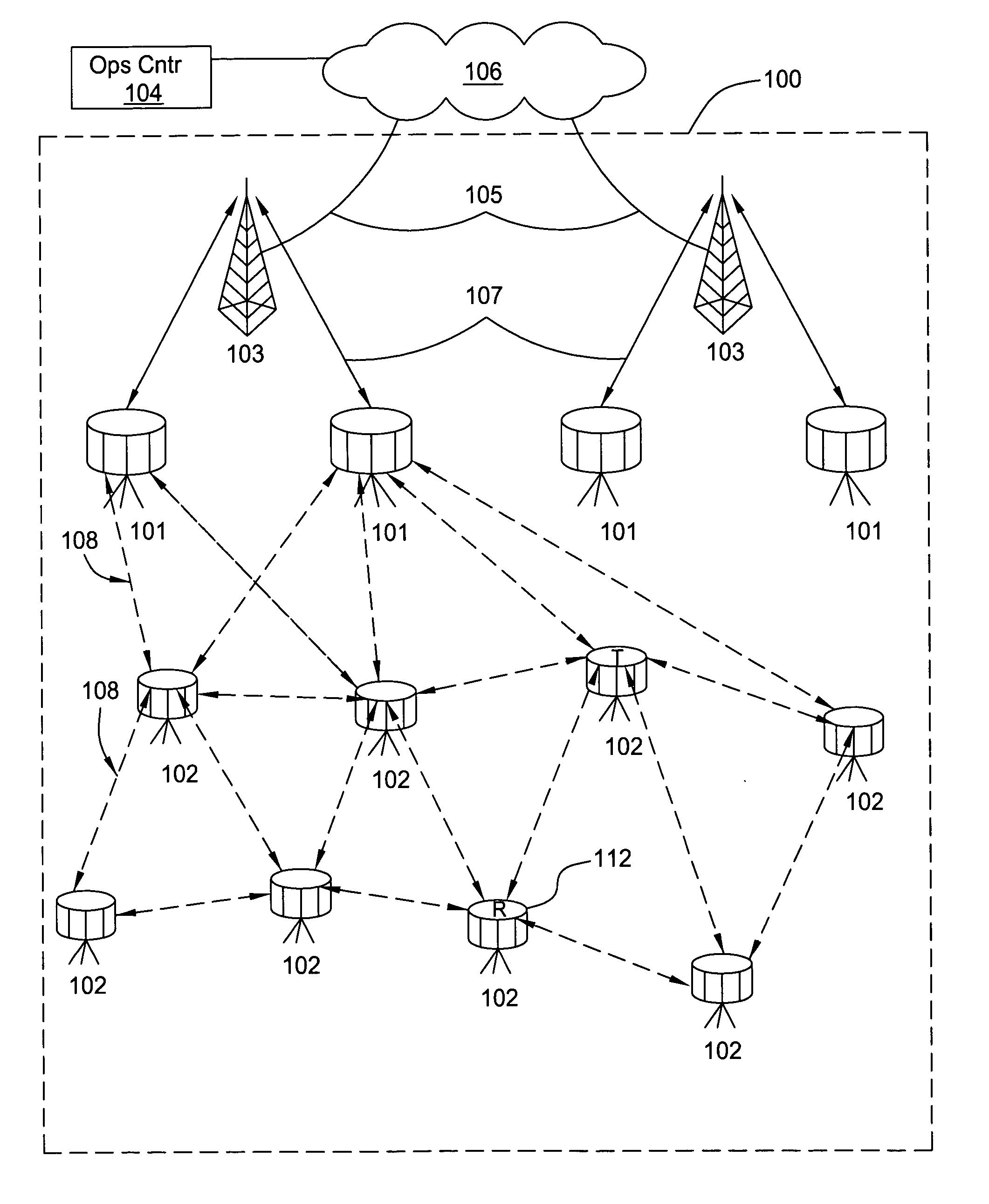
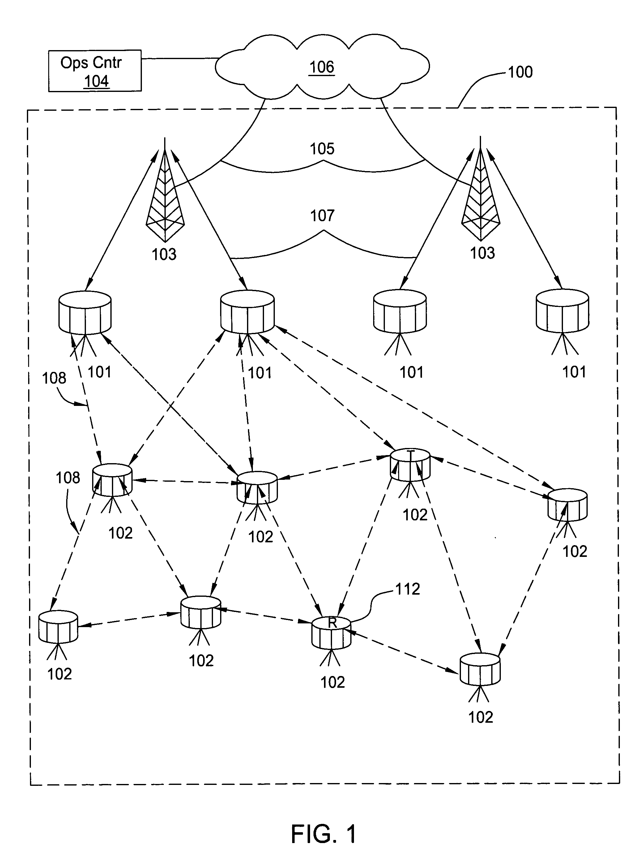
[0021] The present invention provides for a wireless mesh communication protocol that enables information sharing between consumer premise equipment (CPE) devices and the rest of a network such as the internet. Information is transferred between the network and the CPE devices via a succession of mesh nodes (described subsequently). Some of the mesh nodes can serve as routers, although routers having many more variables than conventional wired, internet routers. Whereas a conventional wired router only needs to determine how to route data to the ultimate destination, a mesh node router selects: how to route traffic to the ultimate destination; the devices it directly communicates with; and when and how to communicate with other mesh nodes. Decisions in any of these areas can and do affect the other decisions.

[0022] The wireless mesh communication protocol has two independent features: dynamic bandwidth allocation and information routing. The mesh network architecture and its commun...


PUM


Abstract

A wireless mesh communication protocol that dynamically assigns communication time-slots and frequencies to mesh nodes. A first node is established as a PC that sequentially polls other nodes. A second node responds at a predetermined time with information that includes database records, and then a third node responds similarly. The second node is then established as the PC and the first node is polled during dynamically allocated time-slots and on a frequency that depend on the second node's database records. The third node is then established as a PC and acts similarly. In both cases the first node responds by sending information and data records. The first node is then re-established as the PC. The first node then polls the second and third nodes at times and frequencies that depend on the first node's database records.

Description

BACKGROUND OF THE INVENTION [0001] 1. Field of the Invention [0002] This invention relates generally to wireless networks. More particularly, this invention relates to communication protocols that are suitable for wireless mesh networks. [0003] 2. Description of the Related Art [0004] The appetite for information continues to grow the Internet. Because of such growth new information is constantly being added, which fuels even more growth. Such growth has caused bandwidth problems in many areas. Indeed, yesteryear's limited bandwidth telephone dial-up services are rapidly being replaced with broad bandwidth systems such as digital subscriber lines (DSL) and cable modems. Unfortunately, such systems are not available to a significant portion of the population. Moreover, the acquisition and installation costs associated with such systems make them unappealing to some users and to some service providers. [0005] An alternative to wired communication systems is wireless communications. Wi...

Claims


Application Information

Patent Timeline
Patent Type & Authority Applications(United States)
IPC IPC(8): H04L12/28H04W72/14H04W84/12
CPCH04W72/1205H04W84/12H04W74/06H04W72/12H04L12/28H04W84/18H04L9/40H04W72/23
Inventor RICH, MARK J.FREI, RANDYGORDON, PAUL
Owner TRILLIANT NETWORKS
Learn More