Synchronizing packet traces

a packet trace and synchronization technology, applied in the field of system analysis, can solve the problems of increasing the need for tools and methods for effectively and efficiently analyzing the performance of such networks, increasing the delay that is incurred, and increasing the number of computer and communication networks

Active Publication Date: 2005-02-10
RIVERBED TECH LLC
View PDF13 Cites 22 Cited by
  • Summary
  • Abstract
  • Description
  • Claims
  • Application Information

AI Technical Summary

Benefits of technology

It is an object of this invention to provide a system and method for determining a correspondence among clocks in a multi-node system. It is a further object of this invention to provide a system and method for determining the correspondence among clocks in a multi-node system based on independently monitored traffic at each node. It is a further object of this invention to provide a system and method for associating disassociated time bases in a network. It is a further object of this invention to provide a system and method that provides accurate / feasible estimates of propagation delay times between nodes in a system.

Problems solved by technology

As the complexity of computer and communication networks continually increases, the need for tools and methods for effectively and efficiently analyzing the performance of such networks also increases.
A significant characteristic of a communication path is the delay that is incurred as a message travels along the path; such delay may include transmission, processing, congestion, and other delays that are introduced along the path.
The problem of determining propagation time delays is further complicated by increasingly common use of firewalls and other message buffering schemes that effectively isolate sub-networks within a network, thereby disassociating the time bases in each sub-network.
A further constraint in a common time-based system is that the time of reacting to an event cannot be prior to the time of the event.

Method used


Image

  • Synchronizing packet traces
  • Synchronizing packet traces
  • Synchronizing packet traces

Examples


Embodiment Construction

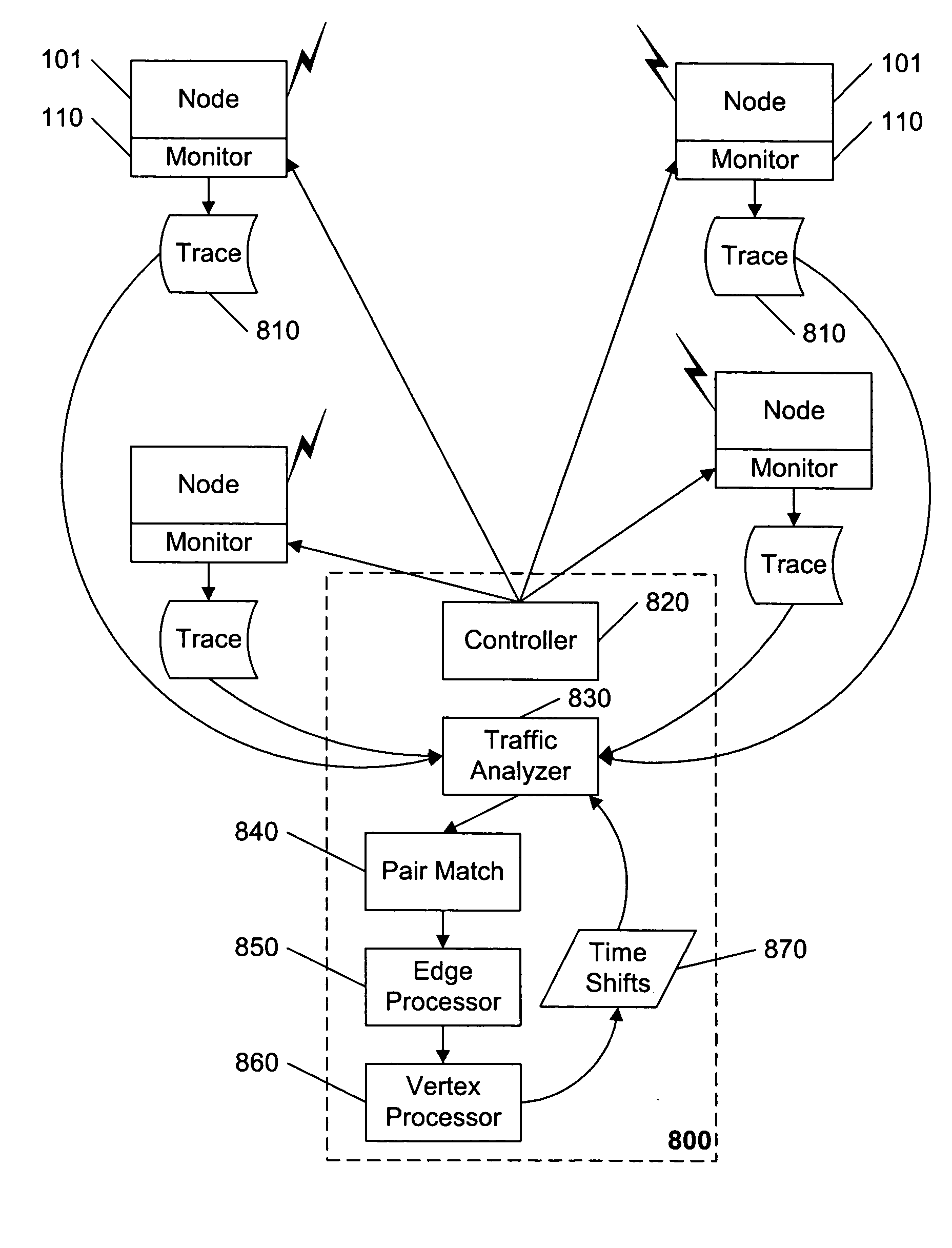
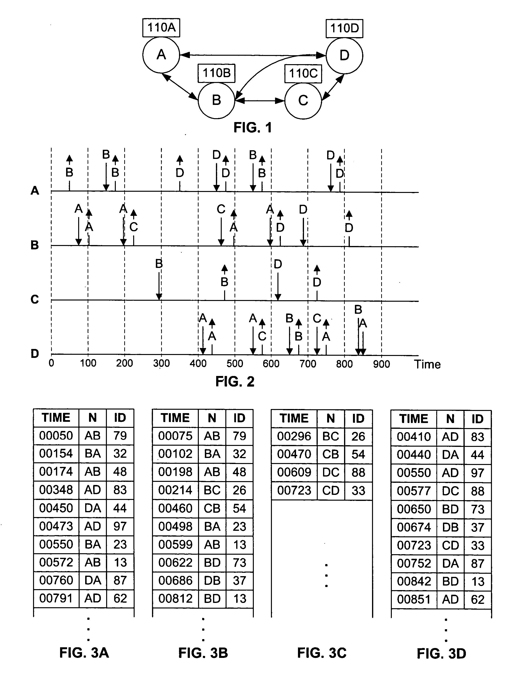
FIG. 1 illustrates an example network comprising nodes A, B, C, and D, each with traffic monitoring devices 110A-D. Although each traffic monitoring device 110 is illustrated as a discrete component in FIG. 1, it may be a software program that runs on the system that sends or receives traffic to and from other nodes, such as provided in the “ACE” traffic analysis system from OPNET, Inc., Bethesda, Md., “Network Monitor” from MicroSoft, Inc., Seattle, Wash., and so on. Stand-alone traffic monitoring devices 110 include, for example, the “Sniffer” system from Network Associates, Inc., Santa Clara, Calif. The traffic monitoring devices 110 record traffic events, including the transmission and reception of packets, and the time of the event, based on the time base used by the traffic monitoring device 110. Some or all of the time bases of the devices 110 are assumed herein to be independent of the other devices 110.

For ease of understanding, the network that is illustrated in FIG. 1 do...


PUM


Abstract

A system and method for determining a common time base among nodes in a network by iteratively propagating timing constraints among the nodes, and determining a time-shift to apply to the time base of each node that conforms to these constraints. “Trace” files record the time of transmission or reception of packets at each node, based on the time base at the node. A fundamental constraint in a common time-based system is that the time of reception of a packet at a destination node cannot be prior to the time of transmission of the packet from a source node. A further constraint in a common time-based system is that the time of reacting to an event cannot be prior to the time of the event. By concurrently tracing traffic among multiple nodes in a network and subsequently processing the trace files to assure that each packet's transmission occurs prior to its reception, and that each reaction packet occurs after its corresponding causal packet, a correspondence between each node's time base and the common time base can be determined.

Description

BACKGROUND AND SUMMARY OF THE INVENTION This invention relates to the field of systems analysis, and in particular to a method and system for synchronizing records of packet transactions among multiple communications devices. As the complexity of computer and communication networks continually increases, the need for tools and methods for effectively and efficiently analyzing the performance of such networks also increases. Traffic monitoring devices, commonly called “sniffers”, have been used for many years to facilitate the diagnosis of communication problems and anomalies. Such monitors provide a record of all of the messages / packets that arrive or depart via a communication channel of a communications device to which they are attached. These monitors also typically record the state of the communication channel. The record, “log”, or “trace” of received or transmitted packets and the ongoing state of the communication channel often provides diagnostic insight into the operatio...

Claims


Application Information

Patent Timeline
Patent Type & Authority Applications(United States)
IPC IPC(8): H04L12/24H04L12/26
CPCH04L41/14H04L43/0852
Inventor MALLOY, PATRICK J.DUNN, ANTOINE D.
Owner RIVERBED TECH LLC
Why Eureka
Try Eureka