Method for determining optimal viewpoints for 3D face modeling and face recognition

Inactive Publication Date: 2005-02-10
MITSUBISHI ELECTRIC RES LAB INC
View PDF10 Cites 102 Cited by
  • Summary
  • Abstract
  • Description
  • Claims
  • Application Information

AI Technical Summary

Benefits of technology

A size of the viewpoint space is reduced for a class of objects, e.g., faces. After uniformly sampling the view-sphere and applying high-level model-specific constraints, such as facial symmetry and imaging geometry, the method generates viewpoint clusters by merging nearby viewpoint cells using a silhouette difference metric

Problems solved by technology

A fundamental problem in multi-view 3D face modeling is to determine a set of optimal viewpoints or ‘poses’ required for accurate 3D shape estimati

Method used


Image

  • Method for determining optimal viewpoints for 3D face modeling and face recognition
  • Method for determining optimal viewpoints for 3D face modeling and face recognition
  • Method for determining optimal viewpoints for 3D face modeling and face recognition

Examples


Embodiment Construction

Multi-View 3D Face Modeling

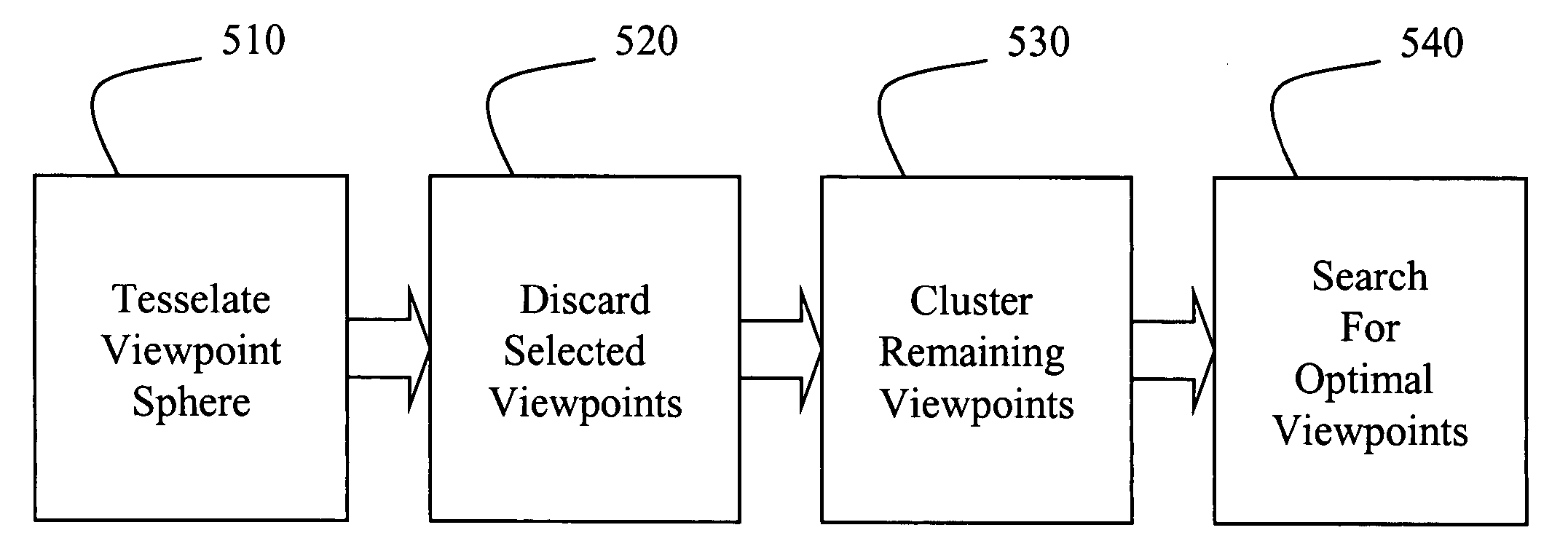
Our present invention provides a method for determining an optimal set of viewpoints required to construct an accurate 3D model of a human face acquired from 2D images taken from the set of viewpoints. Our general method for constructing the 3D model is described in U.S. patent application Ser. No. 10 / 636,355 “Reconstructing Heads from 3D Models and 2D Silhouettes,” filed on Aug. 7, 2003, by Lee et al, incorporate herein by reference.

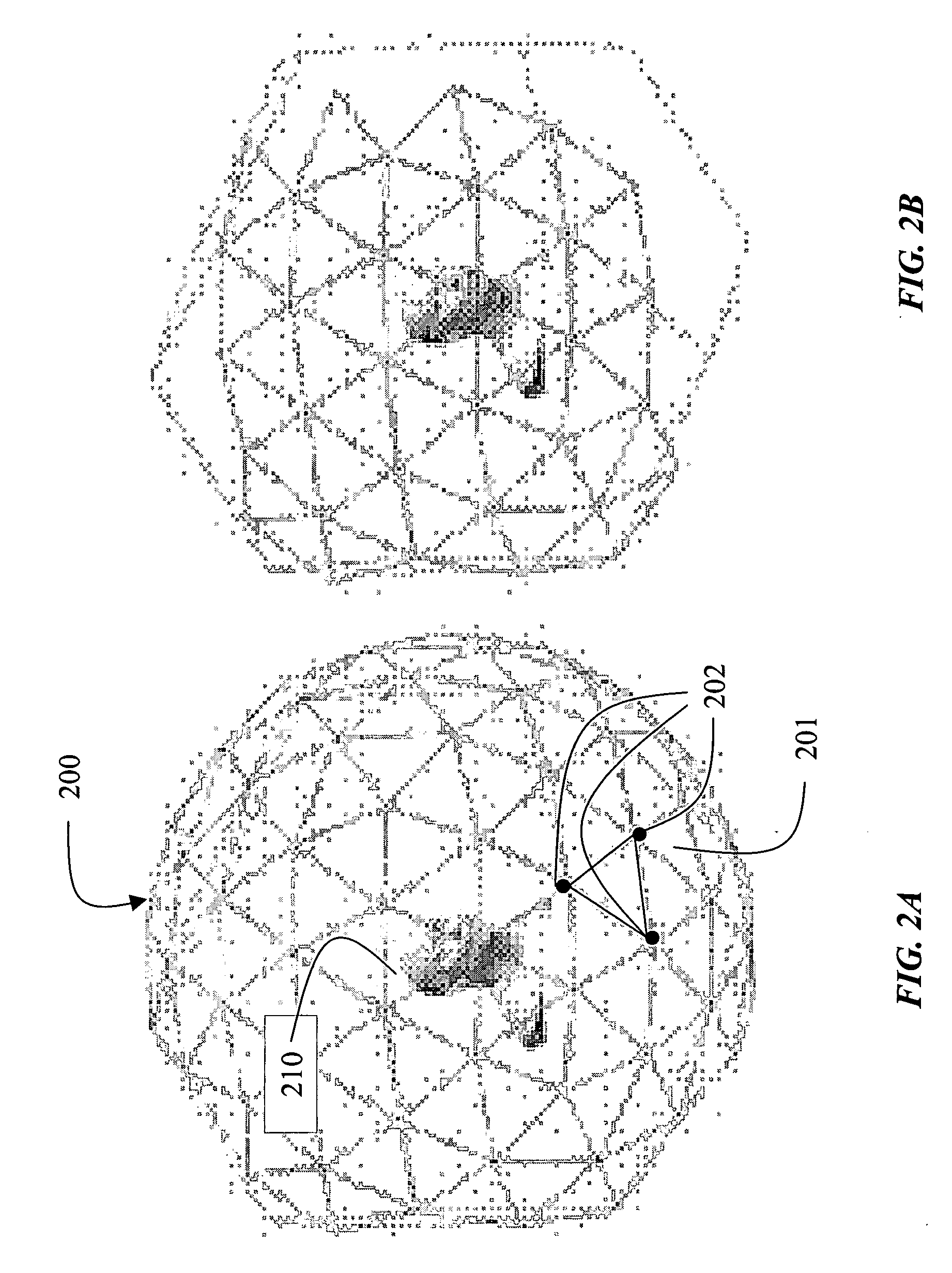
As shown in FIG. 6, our method uses an arrangement of many cameras 600, e.g., eleven, placed on ‘view-sphere”200 around a person's head 210. The placement of the cameras determines the size of the portion of the head that is modeled. In actual practice, the view-sphere is constructed as a geodesic dome with the cameras fitted to the structural members of the dome. The person sits inside the dome on a chair while images are acquired of the person's face. The face 210 is at an approximate center of the view-sphere 200.

As ...


PUM


Abstract

A method determines an optimal set of viewpoints to acquire a 3D shape of a face. A view-sphere is tessellated with a plurality of viewpoint cells. The face is at an approximate center of the view-sphere. Selected viewpoint cells are discarded. The remaining viewpoint cells are clustered to a predetermined number of viewpoint cells according to a silhouette difference metric. The predetermined number of viewpoint cells are searched for a set of optimal viewpoint cells to construct a 3D model of the face.

Description

FIELD OF THE INVENTION This invention relates generally to image processing, and more particularly to modeling and recognizing faces according to 3D models and 2D images. BACKGROUND OF THE INVENTION In computer graphics, it is still a fundamental problem to synthetically construct realistic human heads, particularly the face portion. Hereinafter, when referring to ‘head’ or ‘face’, the invention is most interested in that portion of the head extending from chin-to-brow, and ear-to-ear. Most prior art methods require either extensive manual labor by skilled artists, expensive active 3D scanners, Lee et al., “Realistic Modeling for Facial Animations,” Proceedings of SIGGRAPH 95, pages 55-62, August, 1995, or the availability of high quality of texture images as a substitute for exact face geometry, see Guenter et al., “Making Faces,” Proceedings of SIGGRAPH 98, pages 55-66, July 1998, Lee et al., “Fast Head Modeling for Animation,” Image and Vision Computing, Vol. 18, No. 4, pages 3...

Claims


Application Information

Patent Timeline
IPC IPC(8): G06K9/00G06T17/00
CPCG06T17/00G06K9/00288G06V40/172
Inventor MOGHADDAM, BABACKPFISTER, HANSPETERLEE, JINHO
Owner MITSUBISHI ELECTRIC RES LAB INC
Why Eureka
Try Eureka