Image forming apparatus having a detachable cartridge including a photoconductive drum with axis shaft having a minimal rotational eccentricity, and a method of assembling the image forming apparatus

a technology of image forming apparatus and process cartridge, which is applied in the direction of electrographic process apparatus, instruments, optics, etc., can solve the problems of disturbance of image, affecting image, and the rotary shaft holding the photoconductive drum may not be synchronized, so as to reduce the eccentricity of the photoconductive drum and prevent the turbulence of an electric field and an image defect.

Inactive Publication Date: 2005-02-10
RICOH KK
View PDF12 Cites 94 Cited by
  • Summary
  • Abstract
  • Description
  • Claims
  • Application Information

AI Technical Summary

Benefits of technology

[0012] It is an object of the present invention to provide a novel image forming apparatus in which an image bearing member integrally engaged with a through shaft is detachable from the image forming apparatus and is capable of reducing an eccentricity of the photoconductive drum to prevent turbulence of an electric field and a defect of an image.

Problems solved by technology

On the other hand, the movements of the photoconductive drum and the rotary shaft holding the photoconductive drum may not be synchronized due to a method of fabricating the photoconductive drum and the rotary shaft.
The deviation of each gap may cause a change of an electric field generated in each process and a variation of a transfer pressure, which results in a disturbance in an image.
Therefore, a relationship of tolerances of the shaft and the photoconductive drum may cause a runout of the photoconductive drum affecting the image.
As a result, the relationship of runout tolerances of the photoconductive drum and the shaft leads to an image defect.
With a downsizing of the image forming apparatus, it has been difficult to obtain a space in the image forming apparatus so as to install the photoconductive drum to the rotary shaft extending from the body of the image forming apparatus, which leads to a difficult installation.
Specifically, when a stopping member, such as a retaining ring, for preventing a movement of the photoconductive drum in an axial direction is attached after the photoconductive drum is installed to the rotary shaft, no sufficient space is left in the image forming apparatus and the installation of the stopping member becomes difficult.

Method used


Image

  • Image forming apparatus having a detachable cartridge including a photoconductive drum with axis shaft having a minimal rotational eccentricity, and a method of assembling the image forming apparatus
  • Image forming apparatus having a detachable cartridge including a photoconductive drum with axis shaft having a minimal rotational eccentricity, and a method of assembling the image forming apparatus
  • Image forming apparatus having a detachable cartridge including a photoconductive drum with axis shaft having a minimal rotational eccentricity, and a method of assembling the image forming apparatus

Examples


Embodiment Construction

[0059] In describing preferred embodiments illustrated in the drawings, specific terminology is employed for the sake of clarity. However, the disclosure of this patent specification is not intended to be limited to the specific terminology so selected and it is to be understood that each specific element includes all technical equivalents that operate in a similar manner.

[0060] Referring now to the drawings, wherein like reference numerals designate identical or corresponding parts throughout the several views, preferred embodiments of the present invention area described.

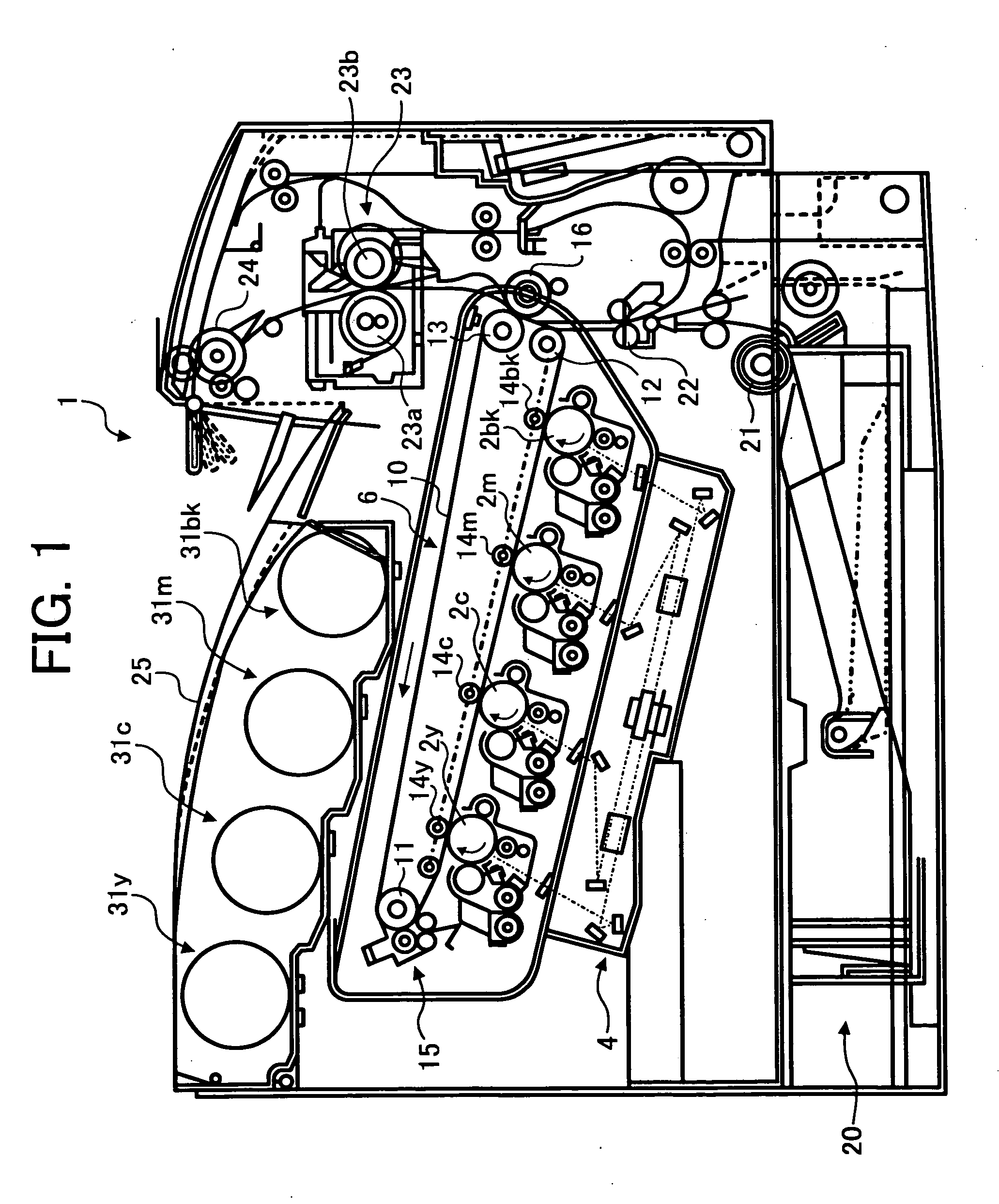
[0061] Referring to FIG. 1, a color printer 1 is described as one example of an electrophotographic image forming apparatus according to an exemplary embodiment of the present invention. The color printer 1 of FIG. 1 employs a tandem system forming a color image with toners of four different colors such as yellow (Y), cyan (C), magenta (M) and black (BK).

[0062] The color printer 1 generally includes four photoc...


PUM


Abstract

An image forming apparatus includes an image forming mechanism and an image bearing member. The image forming mechanism is configured to form an image. The image bearing mechanism is detachably provided to the image forming apparatus. The image bearing mechanism includes an image bearing member configured to bear the image formed by the image forming mechanism, and a through shaft configured to support the image bearing member.

Description

CROSS REFERENCE TO RELATED APPLICATIONS [0001] The present application claims priority under 35 U.S.C. § 119 to Japanese Patent Application No. 2003-187839 filed on Jun. 30, 2003, in the Japan Patent Office, the entire contents of which are incorporated herein by reference.BACKGROUND OF THE INVENTION [0002] 1. Field of the Invention [0003] The present invention relates to an image forming method and apparatus and a process cartridge included in the image forming apparatus, and more particularly to an image forming method and apparatus capable of reducing eccentricity of a photoconductive drum integrally engaged with a through shaft, and a process cartridge including the photoconductive drum and being detachably provided to the image forming apparatus. [0004] 2. Discussion of the Background [0005] A background image forming apparatus, such as a copying machine, a facsimile machine, a printing machine and so forth, generally includes an image bearing member and a developing unit. The ...

Claims


Application Information

Patent Timeline
Patent Type & Authority Applications(United States)
IPC IPC(8): G03G15/00G03G21/16
CPCG03G15/5008G03G15/751G03G21/181G03G21/1671G03G2221/183G03G15/75G03G2221/1606
Inventor NAGASHIMA, HIROYUKISUGIHARA, KAZUYUKIMASUDA, KATSUMIKIMURA, HIDEKISAKAI, KIYOTAKASUDO, KAZUHISAIMAMURA, TSUYOSHI
Owner RICOH KK
Why Eureka
Try Eureka