Document feeder device

Active Publication Date: 2005-02-10
TOSHIBA GLOBAL COMMERCE SOLUTIONS HLDG
19 Cites 5 Cited by

AI-Extracted Technical Summary

Problems solved by technology

A problem with the conventional document feeder device 60 is that if any of the roller shafts 70 and 72 become misaligned, the sheet 52 will skew as it advances through the rollers 62-68.
The problem with the conventional document feeder device 60 is that is difficult to provide an adequately rigid and stable mounting surface for the roller shaft 7...

Method used

[0031] In accordance with the present invention, the document feeder device comprises at least one cantilevered roller shaft that is supported at one end, i.e., the proximate end. This allows the other end, i.e., the distal end, to float thereby eliminating the need for a rigid frame to support the distal end. The proximate end has adequate support to adequately control the position of the cantilevered roller sh...

Benefits of technology

[0010] A document feeder device is disclosed. The document feeder device includes a frame and at least one cantilevered roller shaft for advancing a document, where an unsupported end of the at least one cantilevered roller shaft floats. The document feeder devic...

Abstract

A document feeder device is disclosed. The document feeder device includes a frame and at least one cantilevered roller shaft for advancing a document, where an unsupported end of the at least one cantilevered roller shaft floats. The document feeder device eliminates the need for a rigid frame to support the unsupported end. This decreases the cost of production by eliminating the need for additional frame hardware and/or more rigid frame hardware. The document feeder device can be implemented in existing designs.

Application Domain

Technology Topic

Image

  • Document feeder device
  • Document feeder device
  • Document feeder device

Examples

  • Experimental program(1)

Example

[0018] The present invention relates to document printers, and more particularly to a system and method for providing a document feeder device that can reliably feed documents through a printer. The following description is presented to enable one of ordinary skill in the art to make and use the invention and is provided in the context of a patent application and its requirements. Various modifications to the preferred embodiment and the generic principles and features described herein will be readily apparent to those skilled in the art. Thus, the present invention is not intended to be limited to the embodiment shown but is to be accorded the widest scope consistent with the principles and features described herein.
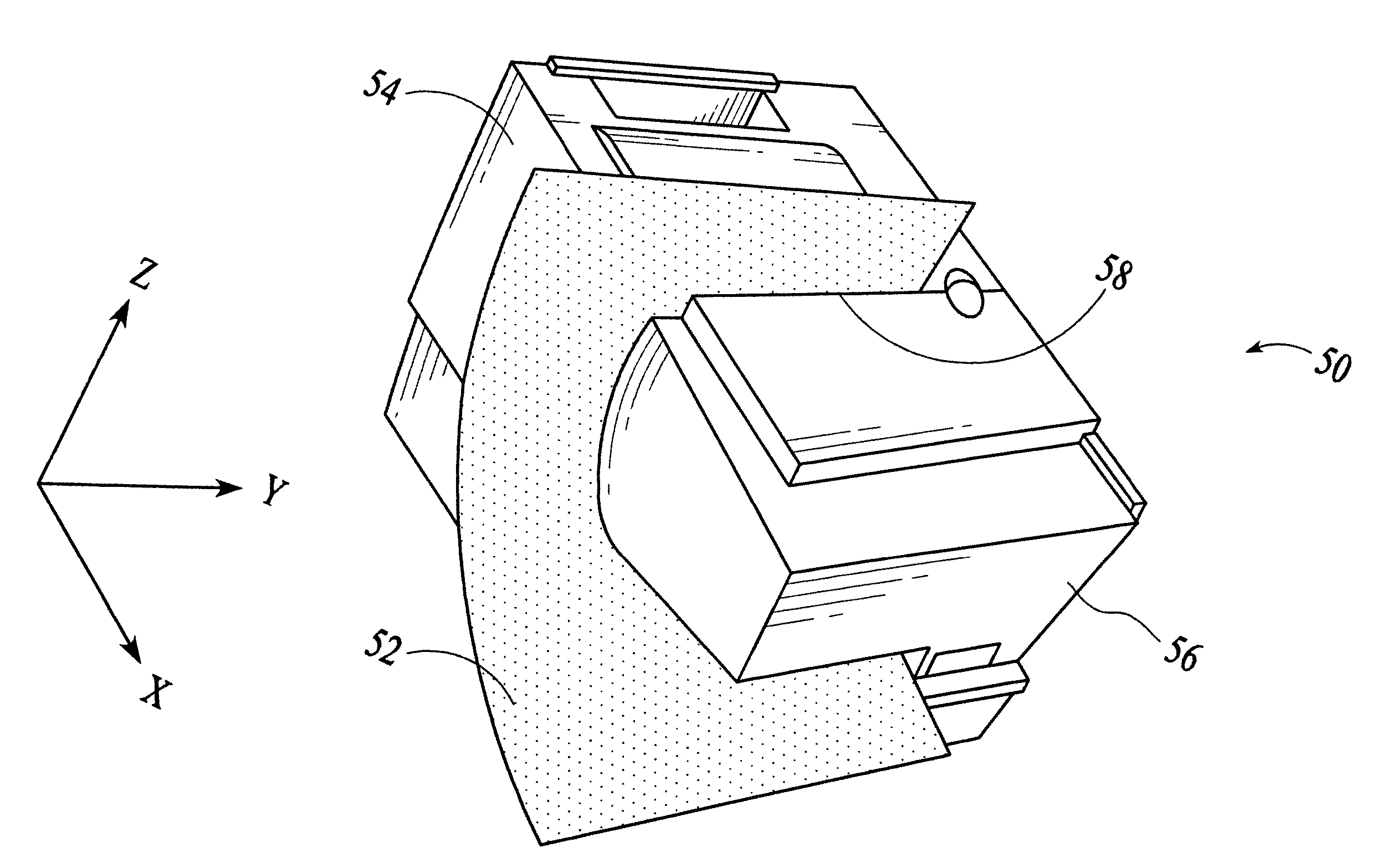
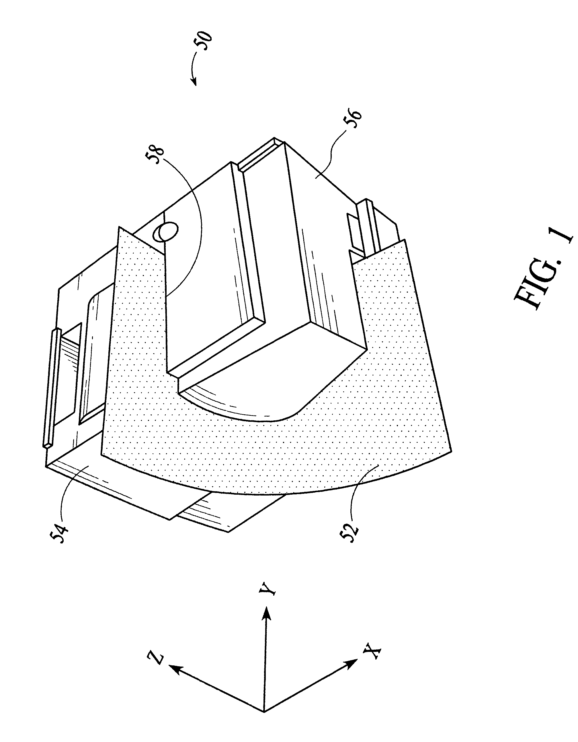
[0019] In accordance with the present invention, the document feeder device comprises at least one cantilevered roller shaft that is supported at one end, i.e., the proximal end. This allows the other end, i.e., the distal end, to float thereby eliminating the need for a rigid frame to support the distal end. The proximate end has adequate support to adequately control the position of the cantilevered roller shaft relative to the rest of the document feeder device. To more particularly describe the features of the present invention, refer now to the following description in conjunction with the accompanying figures.
[0020]FIG. 3 a perspective-view photo of a printer 100 with its cover opened, including a document feeder device 102 in accordance with the present invention, and an 8.5″×11″ sheet 104 in the document feeder device 102. The document feeder device 102 comprises a cantilevered roller shaft 106, which is supported at its proximate end 107 (i.e., right end) (partially hidden; more clearly shown in FIG. 5) such that its distal end 108 (i.e., left end) floats. A cantilevered roller 109 is disposed around the cantilevered roller shaft 106. Alternatively there can be more than one cantilevered roller 109 disposed around the cantilevered roller shaft 106.
[0021] The advantage of the document feeder device 102 is that the distal end 108 floats thereby eliminating the need for a rigid frame that directly supports the distal end 108. This is beneficial because a front portion 110 of the printer 100 can move without disturbing the position of the cantilevered roller shaft 106 relative to the rest of the document feeder device 102. The sheet 104 is secured between the cantilevered roller 109 and a drive roller (hidden) on the other side of the sheet 104.
[0022] The printer 100 can comprise a second document feeder device, including a roller shaft 112 and a roller 114. The rest of the second document feeder device is behind the document 104 and thus hidden. The roller shaft 112 can also be cantilevered like cantilevered roller shaft 106. Alternatively, additional document feeder devices similar to the one described above can be implemented and the specific number of document feeder devices will depend on the specific application.
[0023]FIG. 4 is a flow chart showing a method for feeding a document through a printer in accordance with the present invention. Referring to FIGS. 3 and 4, in a step 120, a printer 100 is provided. In a step 122, a drive roller shaft (hidden) and a cantilevered roller shaft 106 are provided, wherein the cantilevered roller shaft 106 is supported at its proximal end such that its distal end 108 floats. In a step 124, a drive roller (hidden) and a cantilevered roller 109 coupled to the drive roller shaft (hidden) and the cantilevered roller shaft 106, respectively, are provided. In a step 126, a document 104 is inserted in a document path of the printer 100 until the document 104 reaches the drive roller and the cantilevered roller 109. In a step 128, the drive roller and the cantilevered roller 109 are rotated to advance the document 104 along the document path. When the document advances to the end of the document path, the document can then be removed from the document path.
[0024] The advantage of the document feeder device 102 is that it has at least one cantilevered roller shaft 106 that is supported at its proximal end 107. Because the distal end 108 of the cantilevered roller shaft 106 floats, the need for a rigid frame to support the distal end 108 is eliminated. The proximate end 107 has adequate support to control the position of the cantilevered roller shaft 106 relative to the rest of the document feeder device 102.
[0025]FIG. 5 is a perspective-view photo showing in more detail how the proximal end 107 of the cantilevered roller shaft 106 of FIG. 3 is supported. The cantilevered roller shaft 106 comprises two support locations at bearings 140 and 142, which make direct contact with a frame support 144 of the printer. The frame support 144 is an integral part of the main portion of the printer frame. The front portion 110 (shown in FIG. 3) of the printer is not required to provide support for the cantilevered roller shaft 106 because the two support locations at the bearings 140 and 142 provide adequate support. The relative positions of the bearings 140 and 142 are adequately controlled, because the frame support 144 is an integral part of the printer frame and is thus stable. Accordingly, the distal end 108 of the cantilevered roller shaft 106 need not be coupled to the printer frame. The bearings 140 and 142 are relatively close together and located at the proximate end 107 of the cantilevered roller shaft 106 such that the bearings 140 and 142 are located outside the document path. Again, the cantilevered roller shaft 106 is adequately supported without the need for coupling the distal end 108 to the front portion 110 of the printer. Also, the support for the cantilevered roller shaft 106 is provided without obstructing the document path.
[0026] The printer 100 also comprises a drive roller shaft 150, which is coupled to a drive wheel 152 of a drive device (hidden) that is coupled to the frame support 144. The drive device rotates the drive roller shaft 150, which rotates the cantilevered roller shaft 106 to advance a document between the drive roller 154 and the cantilevered roller 109. This specific embodiment has two drive rollers 154. Alternatively, there can be one, or more, drive rollers depending on the specific application.
[0027] In this specific embodiment, the cantilevered roller 109 is a gimbaled roller. Gimbaled rollers are known in the art. The use of a gimbaled roller ensures balanced contact and proper alignment between itself and the drive roller. Even if the drive roller shaft 150 and cantilevered roller shaft 106 were skewed, the gimbaled roller can pivot such that the contact forces between the drive roller 154 and the cantilevered roller 109 rollers are balanced. The cantilevered roller 109 is not limited to a gimbaled roller. Alternatively, the cantilevered roller 109 can be a standard roller, such as the drive roller 154, or any other suitable device.
[0028] In addition to providing reliable paper feeds, the cantilevered roller shaft 106 is also compliant with sheets of different thickness, because the cantilevered roller shaft 106 has freedom of movement normal to a sheet. FIG. 6 is a perspective-view photo of the proximate end 107 of the cantilevered roller shaft 106 of FIGS. 3 and 5 where a tension spring 160 is visible. The tension spring 160 connects to the bearing 140 and to the frame support 144. The cantilevered roller shaft 106 is thus spring loaded against drive roller 150. Accordingly, sheets of paper of various thicknesses can be fed through the document feeder device. In a preferred embodiment, sheets of paper up to 0.2 mm thick, or more, can be fed through the document feeder device.
[0029] Alternatively, the relative positions of the drive roller shaft 150 and the cantilevered roller shaft 106 can be switched such that the cantilevered roller shaft 106 is driven by the drive wheel 152. Thereby the cantilevered roller shaft 106 functions as a drive roller shaft, and the drive roller shaft 150 functions as a cantilevered roller shaft 106. Alternatively, both the cantilevered roller shaft 106 and the drive roller shaft 150 can be cantilevered.
[0030] Another advantage of the document feed device in accordance with the present invention is that it can be set at different heights relative to the printer frame because of the reliable stability provided by the cantilevered roller shaft 106. This flexibility can provide additional space for additional devices, such as a scanner, to be integrated into the printer 100. FIG. 7 is a perspective-view photo of the printer 100 of FIGS. 3 and 5 with a scanner 172 in accordance with the present invention. In this specific embodiment, the scanner 172 is an optical scanner.
[0031] In accordance with the present invention, the document feeder device comprises at least one cantilevered roller shaft that is supported at one end, i.e., the proximate end. This allows the other end, i.e., the distal end, to float thereby eliminating the need for a rigid frame to support the distal end. The proximate end has adequate support to adequately control the position of the cantilevered roller shaft relative to the rest of the document feeder device. The document feeder device in accordance with the present invention eliminates the need for a rigid frame to supports the distal ends of the cantilevered roller shaft(s). This decreases the cost of production by eliminating the need for additional frame hardware or more rigid frame hardware. The document feeder device can be implemented in existing designs.
[0032] Another advantage of the document feeder device is that it allows for additional devices such as an optical scanner to be integrated with the printer without compromising the reliability of the document feeder assembly.
[0033] Note that the present invention is not limited to printers and may apply to other systems and still remain within the spirit and scope of the present invention.
[0034] Although the present invention has been described in accordance with the embodiments shown, one of ordinary skill in the art will readily recognize that there could be variations to the embodiments and those variations would be within the spirit and scope of the present invention. Accordingly, many modifications may be made by one of ordinary skill in the art without departing from the spirit and scope of the appended claims.

PUM

no PUM

Description & Claims & Application Information

We can also present the details of the Description, Claims and Application information to help users get a comprehensive understanding of the technical details of the patent, such as background art, summary of invention, brief description of drawings, description of embodiments, and other original content. On the other hand, users can also determine the specific scope of protection of the technology through the list of claims; as well as understand the changes in the life cycle of the technology with the presentation of the patent timeline. Login to view more.

Similar technology patents

Braking apparatus

ActiveUS20080257669A1Decrease costLess partBraking action transmissionTelemotorsBrake pressureElectricity
Owner:DELPHI TECH INC +1

Classification and recommendation of technical efficacy words

Why Eureka
Try Eureka