Automatic urine disposal device and urine receptacle used therefor

a technology of automatic urine collection and urine receptacle, which is applied in the field of automatic urine collection device and urine receptacle used therefor, can solve the problems of wearer discomfort, increased probability of injuring the urethra or the bladder, and increased urine collection. the effect of the percentag

Inactive Publication Date: 2005-02-10
HITACHI LTD +1
View PDF5 Cites 40 Cited by
  • Summary
  • Abstract
  • Description
  • Claims
  • Application Information

AI Technical Summary

Benefits of technology

[0008] The objective of the present invention is to provide a compact and lightweight automatic urine disposal device which increases the percentage of urine collection by the urine collecting pad and also to provide a urine collecting pad used therefor.

Problems solved by technology

Because of age, physical disability, hospitalization due to injury or illness, or other physical conditions, people sometimes become unable to voluntarily control the bladder or clean up urine on their own.
When a catheter is directly inserted into the bladder, the wearer feels great discomfort and there is also the probability of injuring the urethra or bladder or the occurrence of an infection.
When a paper diaper is worn for a prolonged period of time, urine may leak, the wearer can become uncomfortable, get stuffy, or skin troubles such as rashes may occur.
To avoid this, the paper diaper must be frequently changed, which will impose considerable physical and mental burdens on both the wearer and the caretaker.
Imposed on a daily basis, those physical and mental burdens become a big concern and a significant economical burden as well.
For this reason, the amount of urine which remains in the urine collecting pad (urine absorbent material) is large, which makes the wearer feel uncomfortable.
Thus, in fact, the conventional urine disposal device has no practical use as a portable urine disposal device.
As stated above, in the conventional techniques, there are problems in that the amount of urine which remains in the urine collecting pad is large and to reduce the amount, the urine disposal device must be large and heavy.

Method used


Image

  • Automatic urine disposal device and urine receptacle used therefor
  • Automatic urine disposal device and urine receptacle used therefor
  • Automatic urine disposal device and urine receptacle used therefor

Examples


Embodiment Construction

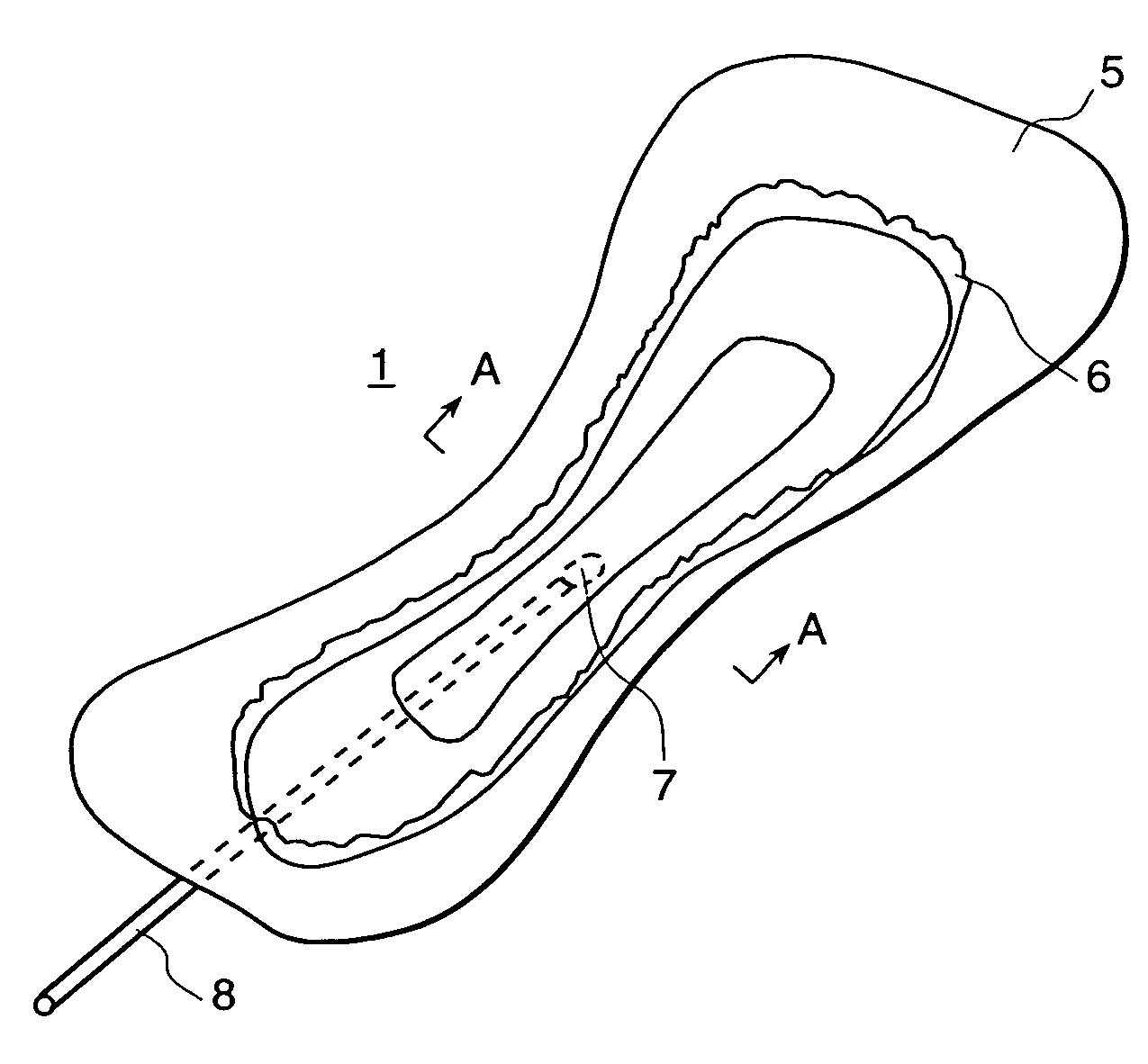
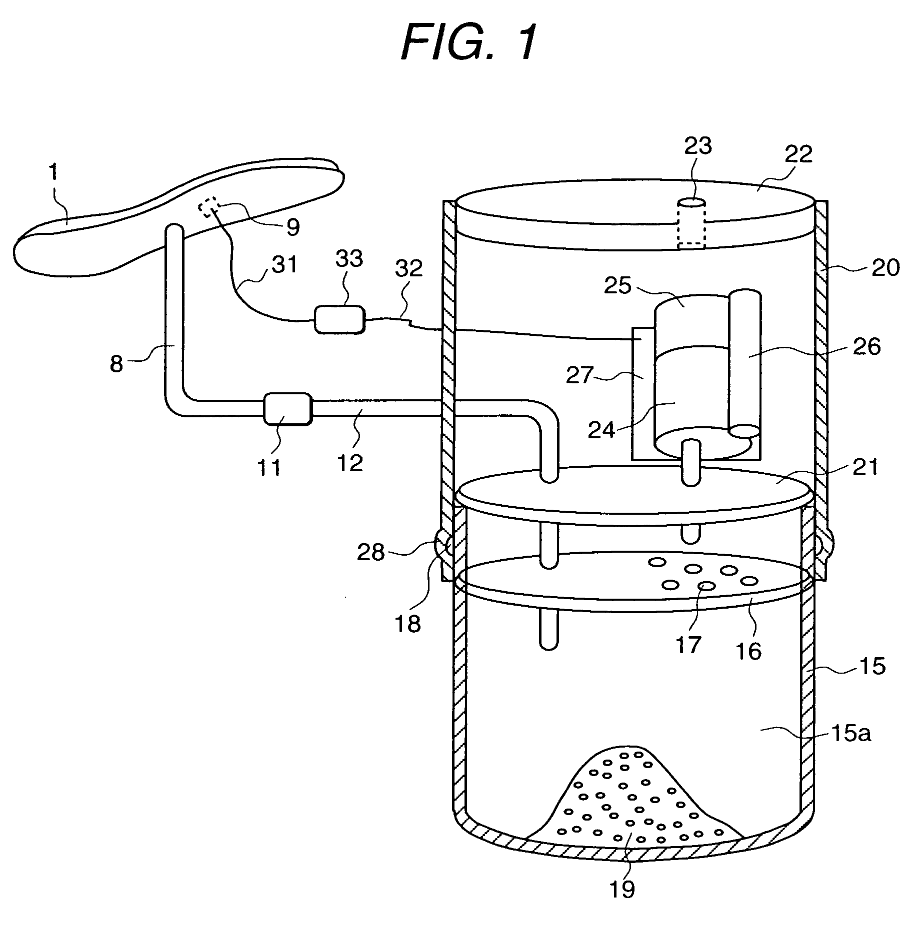
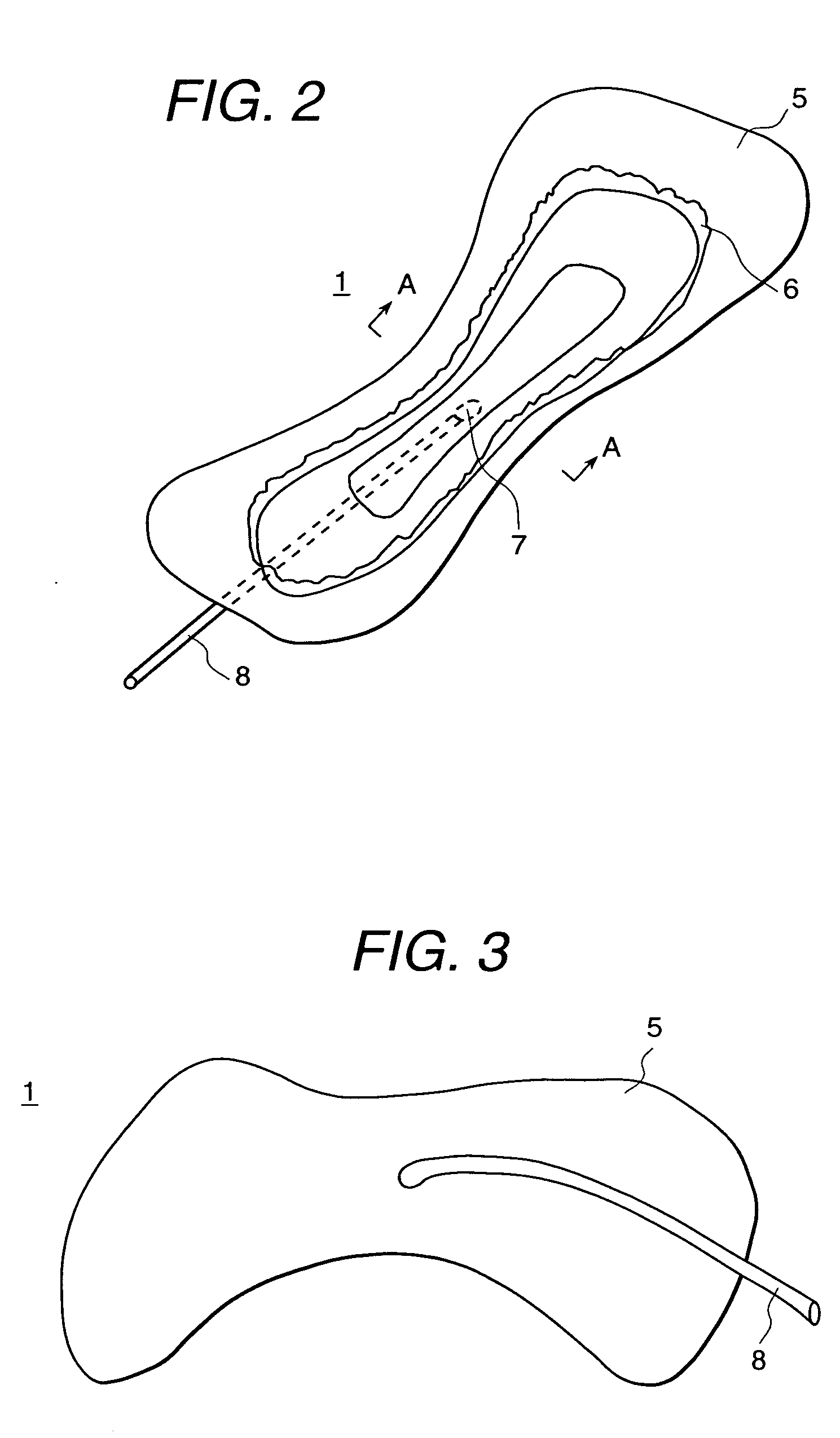
[0016] An embodiment of the present invention is shown in FIGS. 1 through 5. FIG. 1 is a schematic diagram of an automatic urine disposal device according to the present invention. FIG. 2 is a top view of the urine collecting pad, FIG. 3 is a bottom view of the urine collecting pad, FIG. 4 is an exploded perspective view of the urine collecting pad, and FIG. 5 is an enlarged cross-sectional view taken along A-A line in FIG. 2.

[0017] In FIGS. 1 through 5, a urine collecting pad 1 which absorbs urine discharged from a wearer's urinating part, not shown, is substantially rectangular, as shown in FIGS. 2 and 3, and its width at the middle portion in the longitudinal direction (direction of the wearer's front and rear) 2 is narrow so that it is shaped like an hourglass. The reason for this shape is to fit the wearer's crotch.

[0018] As shown in FIG. 4, the urine collecting pad 1 consists of a top sheet 2, hydrophilic sheet 3, urine absorbent sheet 4, outer sheet 5 and gathers 6. The top...


PUM

PropertyMeasurementUnit
diameteraaaaaaaaaa
diameteraaaaaaaaaa
urine flow rateaaaaaaaaaa

Abstract

An automatic urine disposal device has a urine collecting pad, vacuum pump, and urine tank. In the urine collecting pad, the top sheet comes in contact with the wearer's skin, the hydrophilic sheet is disposed on the bottom of the top sheet, and the urine absorbent sheet is disposed at the bottom. When discharged urine flows in the top sheet, the hydrophilic sheet widely diffuses urine to saturate its entire surface and then becomes non-breathable. As the vacuum pump vacuums the air from the urine tank, urine is directed from a urine drainage port of the urine collecting pad via a urine drainage tube to the urine tank which is a sealed container.

Description

[0001] The present application claims priority from Japanese application JP2003-206340 filed on Aug. 6, 2003, the content of which is hereby incorporated by reference into this application. BACKGROUND OF THE INVENTION [0002] The present invention relates to an automatic urine disposal device worn by the bedridden elderly, hospitalized patients, physically disabled people, and others who are unable to voluntarily control the bladder or to clean up urine on their own and also relates to a urine receptacle or a collecting pad used therefor. [0003] Because of age, physical disability, hospitalization due to injury or illness, or other physical conditions, people sometimes become unable to voluntarily control the bladder or clean up urine on their own. In those situations, generally, a catheter is directly inserted into the bladder to discharge urine or paper diaper is used. [0004] When a catheter is directly inserted into the bladder, the wearer feels great discomfort and there is also ...

Claims


Application Information

Patent Timeline
Patent Type & Authority Applications(United States)
IPC IPC(8): A61F5/44A61F5/455
CPCA61F5/455A61F13/5116A61F13/51305A61F2013/51173A61F2013/51178A61F2013/530437
Inventor MACHIDA, SHIGERUKOBAYASHI, JUNICHIYOSHITOMI, YUJIKOUNO, AKIOMIMIYAGAWA, RYOUSUKEWADA, ICHIROSUZUKI, MIOU
Owner HITACHI LTD
Why Eureka
Try Eureka