Hip joint prosthesis

a hip joint and prosthesis technology, applied in the field can solve problems such as affecting the proper function of hip joint prosthesis, and achieve the effect of preventing the loading of the cartilage layer in the hip sock

Inactive Publication Date: 2005-02-10
SIEBEL THOMAS
View PDF4 Cites 28 Cited by
  • Summary
  • Abstract
  • Description
  • Claims
  • Application Information

AI Technical Summary

Benefits of technology

[0007] According to the invention, no fixed anchoring of the socket part in the hipbone takes place. The socket part that is polished on both sides to provide gliding surfaces can be inserted into the natural hip socket without there being the risk of deformation. By providing an outer gliding surface on the socket part, loading of the cartilage layer in the hip socket is prevented.
[0008] In a particularly preferred embodiment of the invention, a stop limiting the rotation of the socket part in the natural hip socket is formed; the stop prevents that the socket part will project too far from the hip socket and will damage with its edge the surrounding tissue.

Problems solved by technology

When pressing the socket part into place, permanent deformations of the spherical surface of the socket part receiving the head can occur; this impairs the proper function of the hip joint prosthesis.

Method used


Image

  • Hip joint prosthesis
  • Hip joint prosthesis
  • Hip joint prosthesis

Examples


Embodiment Construction

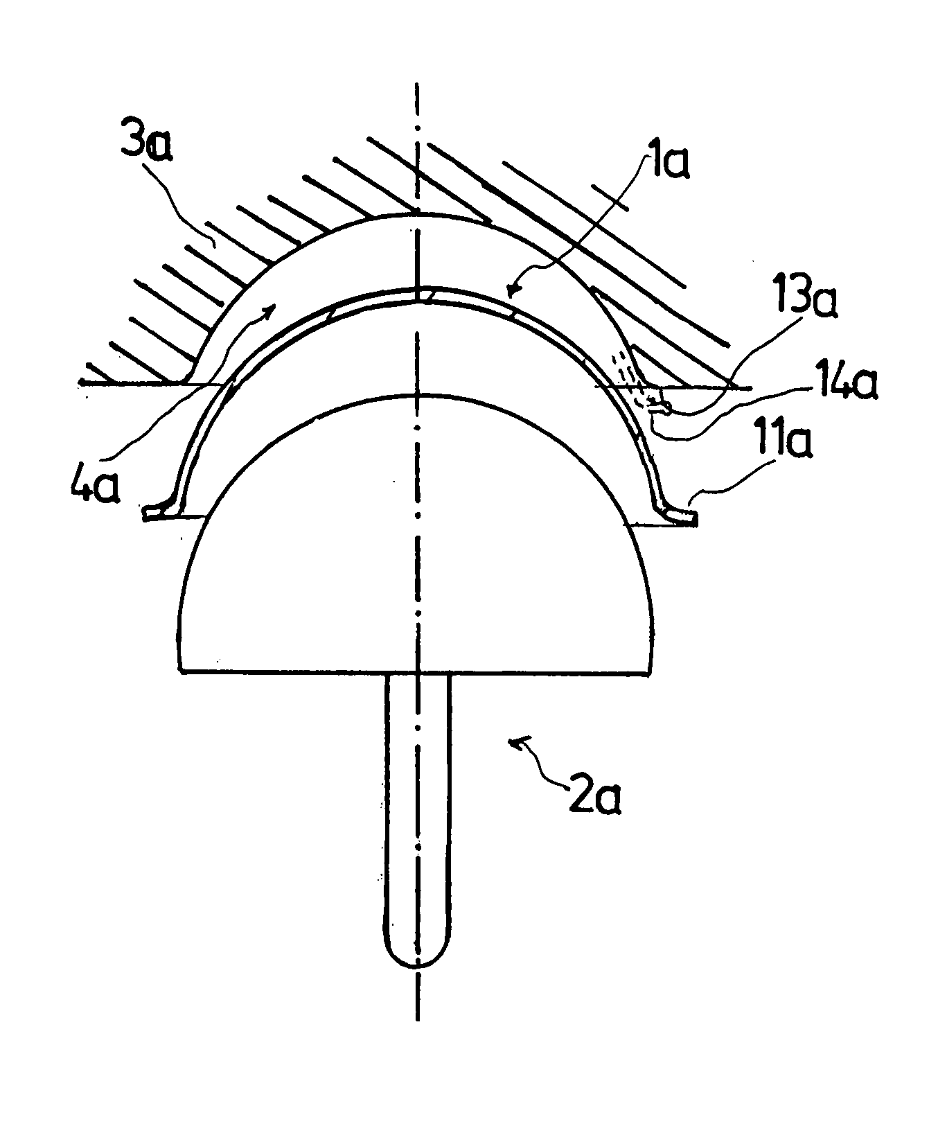
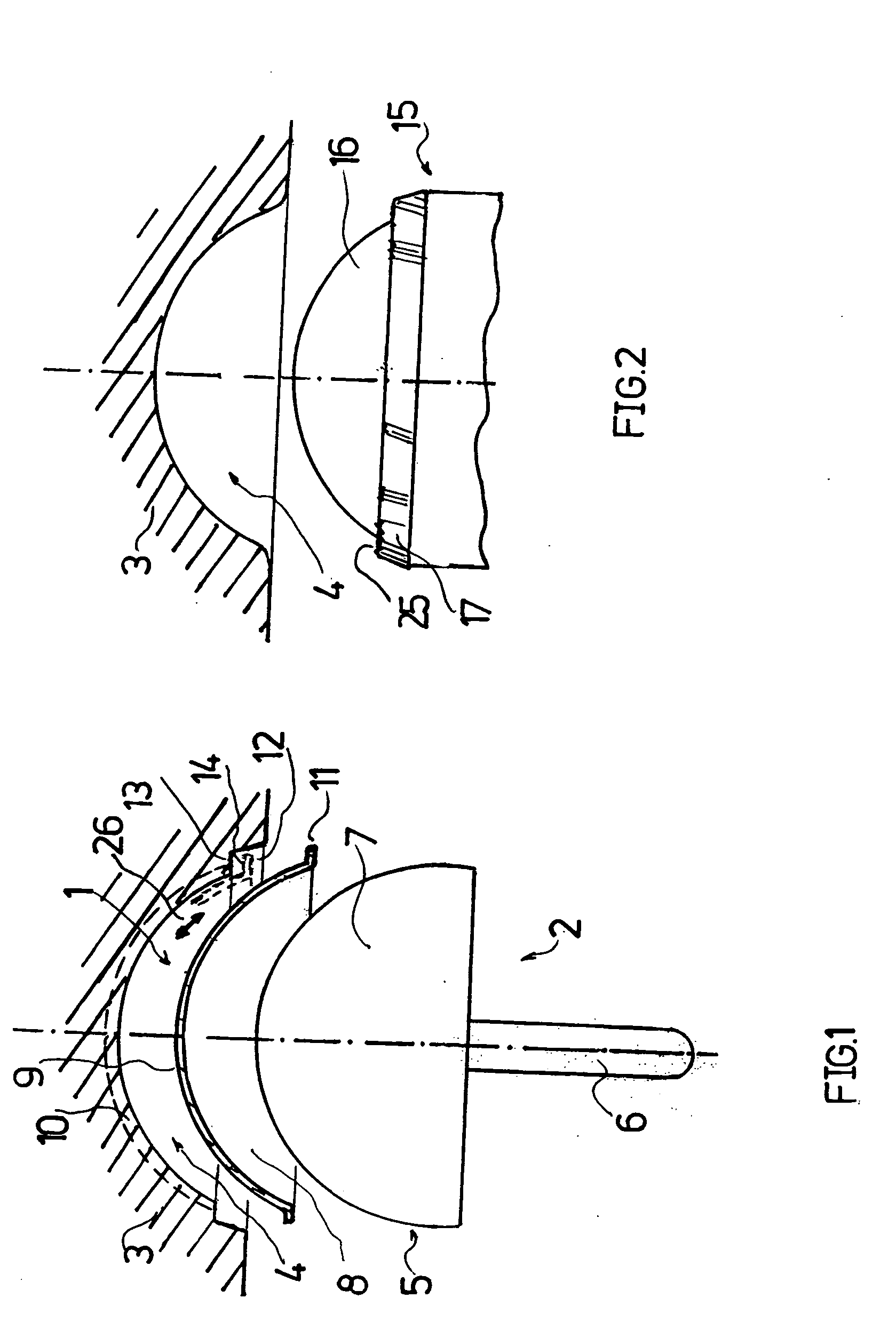
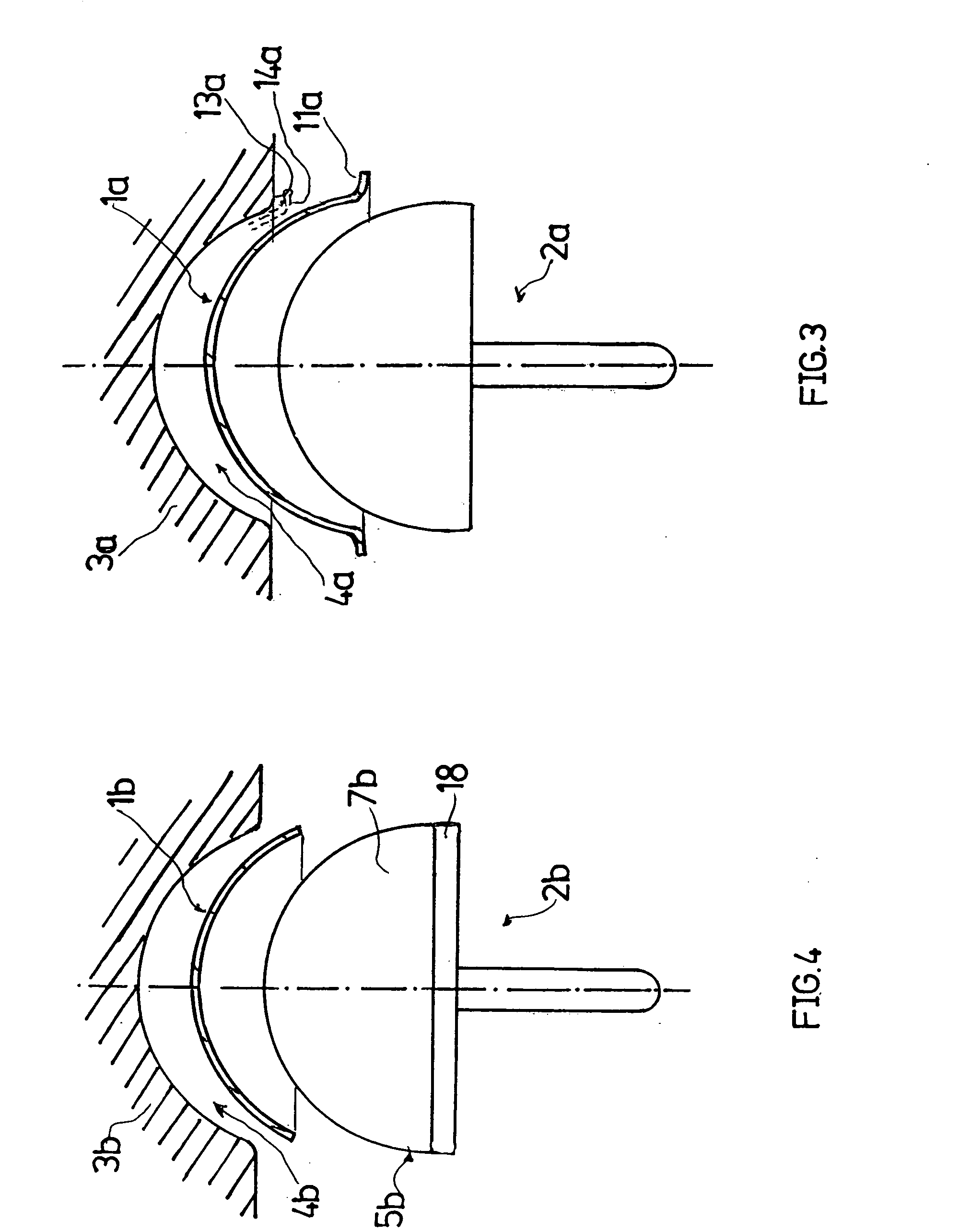
[0025] The hip joint illustrated in FIG. 1 has a socket part 1 and a head 2. The socket part can be inserted into the natural hip socket 4 formed in the hipbone 3. The head 2 has a spherical joint cap 5 to be placed onto a prepared femoral head and a central pin 6 connected to the spherical cap for anchoring the head in the bone of the femoral head.

[0026] The spherical outer surfaces 7 of the spherical cap 5 is polished for increasing the gliding properties. When the hip joint prosthesis is implanted, the outer surface 7 rests against a spherical polished inner surface 8 of the socket part 1.

[0027] The spherical outer side 9 of the socket part 1 facing away from the head is also polished so that a gliding surface is formed with which the implanted socket part 1 rests against the cartilage layer 10 in the hip socket 4.

[0028] As illustrated in FIG. 1, the socket part 1 is provided with a flange-like angled edge portion 11. The angled edge portion 11 is received in an edge depressio...


PUM


Abstract

A hip joint prosthesis has a socket part and a head rotatably arranged within the socket part. The socket part has an outer side facing away from the head and the outer side has a gliding surface configured to rotatably support the socket part in a natural hip socket. The socket part is polished on the outer side for forming the gliding surface. A stop is provided on the head or on the hipbone for limiting rotation of the socket part. The socket part has an angled edge portion that is arranged in an edge depression of the hip socket and strikes on the hipbone. The rotation of the socket part is limited in this way.

Description

BACKGROUND OF THE INVENTION [0001] 1. Field of the Invention [0002] The invention relates to a hip joint prosthesis comprising a socket part and a head or ball rotatably supported in the socket part. [0003] 2. Description of the Related Art [0004] Hip joint prostheses that are known in practice have a socket part or cup provided for being pressed into the optionally widened natural hip socket. The surface of the socket part on the side facing away from the head or ball is provided with a rough coating that stimulates ingrowth of the bone tissue. When pressing the socket part into place, permanent deformations of the spherical surface of the socket part receiving the head can occur; this impairs the proper function of the hip joint prosthesis. SUMMARY OF THE INVENTION [0005] It is an object of the present invention to provide a new hip joint prosthesis of the aforementioned kind whose socket part can be implanted in a load-free way. [0006] In accordance with the present invention, th...

Claims


Application Information

Patent Timeline
Patent Type & Authority Applications(United States)
IPC IPC(8): A61B17/16A61F2/00A61F2/32
CPCA61B17/1666A61F2250/0058A61F2002/30535A61F2/32
Inventor SIEBEL, THOMAS
Owner SIEBEL THOMAS
Why Eureka
Try Eureka