Embedded DRAM cache memory and method having reduced latency

Inactive Publication Date: 2005-02-10
MICRON TECH INC
View PDF12 Cites 34 Cited by
  • Summary
  • Abstract
  • Description
  • Claims
  • Application Information

AI Technical Summary

Problems solved by technology

If the access will result in a cache miss, the data from the system memory is coupled to the processor.

Method used


Image

  • Embedded DRAM cache memory and method having reduced latency
  • Embedded DRAM cache memory and method having reduced latency
  • Embedded DRAM cache memory and method having reduced latency

Examples


Embodiment Construction

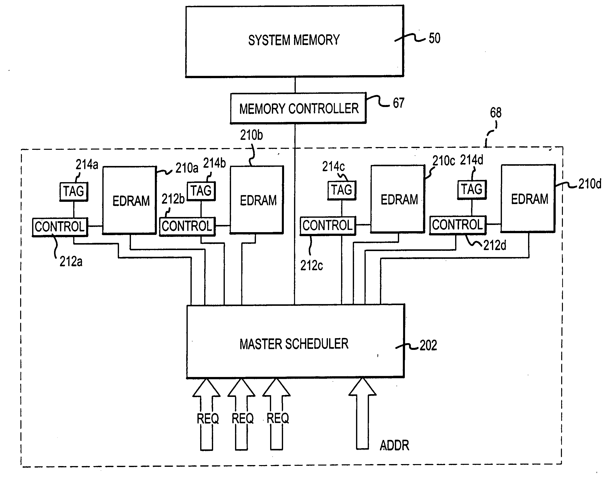
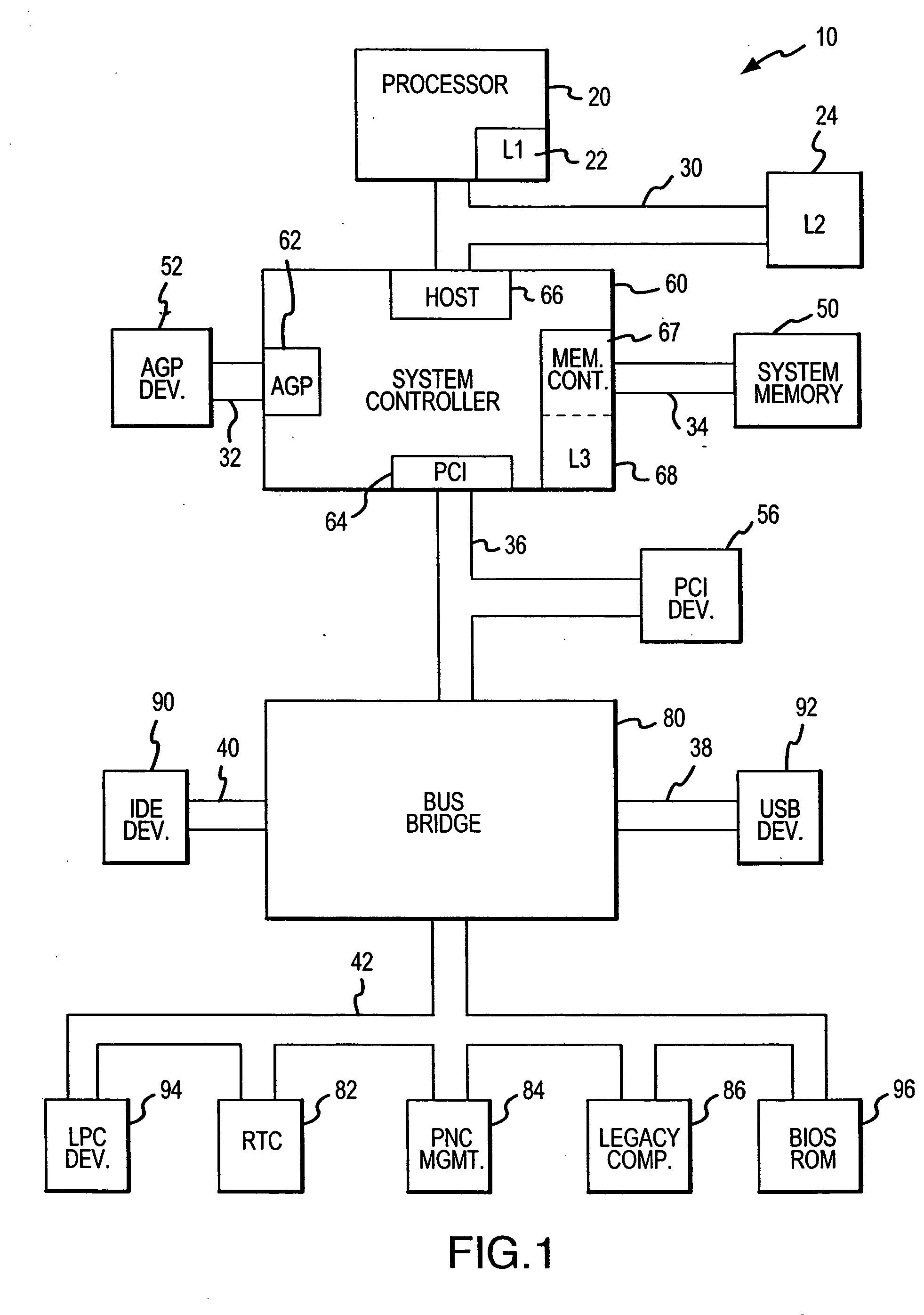
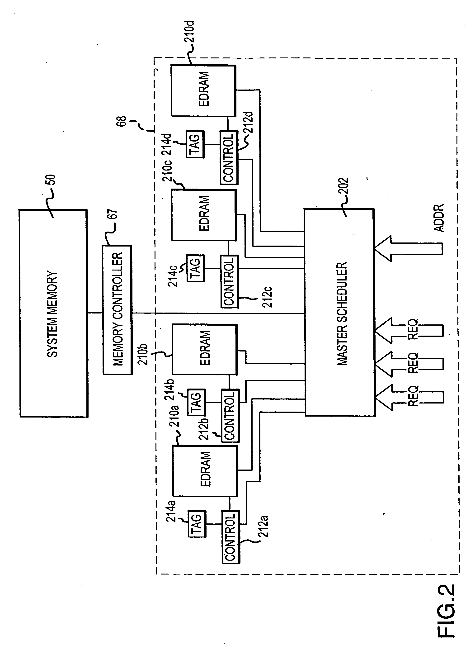
[0019]FIG. 2 is a block diagram illustrating an exemplary L3 cache 68 utilized in the system 10 of FIG. 1 according to one embodiment of the invention. The L3 cache 68 is shown in FIG. 2 coupled to the system memory 50 through the memory controller 67. The L3 cache 68 comprises a plurality of eDRAM arrays 210a, 210b, 210c, 210d (collectively referred to herein as “eDRAM arrays 210”). Although FIG. 2 illustrates four eDRAM arrays 210a-d, it should be appreciated that any number of arrays 210 can be used so that the number of arrays 210 can be application specific. In one embodiment, the L3 cache 68 includes eight independent one Mb eDRAM arrays 210, with each array 210 being 128 bits wide. Thus, in one embodiment, the L3 cache 200 size is eight Mb, which is substantially larger than the sizes of conventional L1 and L2 caches, which typically may have sizes of 128 Kb and 512 Kb, respectively. It should be appreciated that the sizes of the L1, L2 and L3 caches 22, 24, 68 are purely exe...


PUM


Abstract

A computer system includes a processor, a system memory, and an integrated circuit system controller coupled to the processor and the system memory. The system controller includes a system memory controller coupled to the system memory, a processor interface coupled to the processor and an embedded cache memory integrated with the memory controller and the processor interface. The cache memory includes at least one DRAM array, at least one tag memory, and at least one cache memory controller. The cache memory controller initiates an access to either or both the DRAM array and the tag memory, as well as the system memory, before the cache memory controller has determined if the access will result in a cache hit or a cache miss. If the cache memory controller determines that the access will result in a cache hit, data are coupled from the DRAM array to the processor. If the cache memory controller determines that the access will result in a cache miss, data are coupled from the system memory to the processor.

Description

TECHNICAL FIELD [0001] The present invention relates generally to cache memory for a processor-based system and, more particularly, to an apparatus and method that efficiently utilizes embedded dynamic random access memory (“eDRAM”) as a level three (L3) cache in the system controller of a processor based system. BACKGROUND OF THE INVENTION [0002] The speed at which processors can execute instructions has typically outpaced the speed at which memory systems can supply the instructions and data to the processors. Due to this discrepancy in the operating speeds of the processors and system memory, the system memory architecture plays a major role in determining the actual performance of the system. Most current memory hierarchies utilize cache memory in an attempt to minimize memory access latencies. [0003] Cache memory is used to provide faster access to frequently used instructions and data, which helps improve the overall performance of the system. Cache memory is able to provide f...

Claims


Application Information

Patent Timeline
Patent Type & Authority Applications(United States)
IPC IPC(8): G06F12/00G06F12/08G06F13/00
CPCG06F12/0897G06F12/0893
Inventor JEDDELOH, JOSEPH
Owner MICRON TECH INC
Why Eureka
Try Eureka