
Drywall measuring tape

a technology of measuring tape and drywall, applied in the field of measuring tapes, can solve the problems of lack of t-square or other attachment of the measuring tape device, lack of laser beam to project a mark, device, etc., and achieve the effect of quick alignment and convenient taking measurements

Inactive Publication Date: 2005-02-17
CONNOR MICHAEL L
View PDF18 Cites 19 Cited by
  • Summary
  • Abstract
  • Description
  • Claims
  • Application Information

AI Technical Summary

Benefits of technology

[0012] The drywall measuring tape is a tape measuring device incorporating focused light beam sources to facilitate taking measurements relative to a remote surface, and a T-square guide for bringing the drywall measuring tape quickly into alignment with a surface edge, a wall or wall stud, or the like.
[0014] Additionally, the drywall measuring tape includes a T-square bracket on the housing base, disposed so that the drywall measuring tape can be quickly aligned with a surface edge, a wall or wall stud, or the like for a measurement perpendicular to the surface edge, a wall or wall stud, or the like.
[0018] It is a further object of the invention to provide a drywall measuring tape that has a T-square guide so that the drywall measuring tape can be quickly aligned with an edge.
[0019] It is an object of the invention to provide improved elements and arrangements thereof for the purposes described which is inexpensive, dependable and fully effective in accomplishing its intended purposes.

Problems solved by technology

However, because only a single laser light source is used, the measuring tape's housing must be held in a particular orientation to cast the beam at its target.
Additionally, this measuring tape device lacks a T-square or other attachment that would allow the tape measure to be quickly positioned for measurements taken in relation to a surface edge, a wall or wall stud, or the like.
In this arrangement, while the laser device provides a laser pointer conveniently contained in the tape measure's housing, the laser beam does not function to project a mark that can be used for taking a measurement relative to a remote surface.
The device, however, does not perform any measuring function.

Method used


Image

  • Drywall measuring tape
  • Drywall measuring tape
  • Drywall measuring tape

Examples


Embodiment Construction

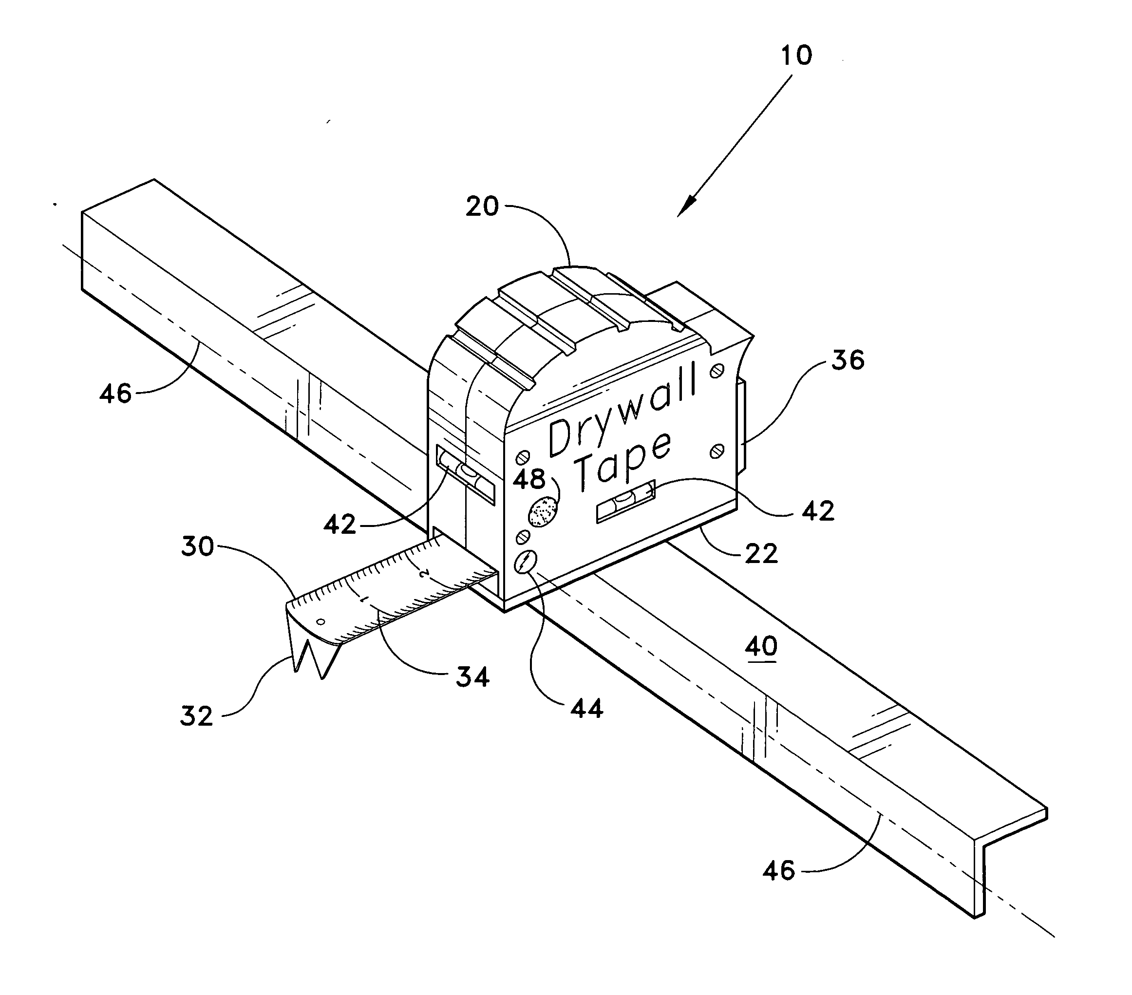
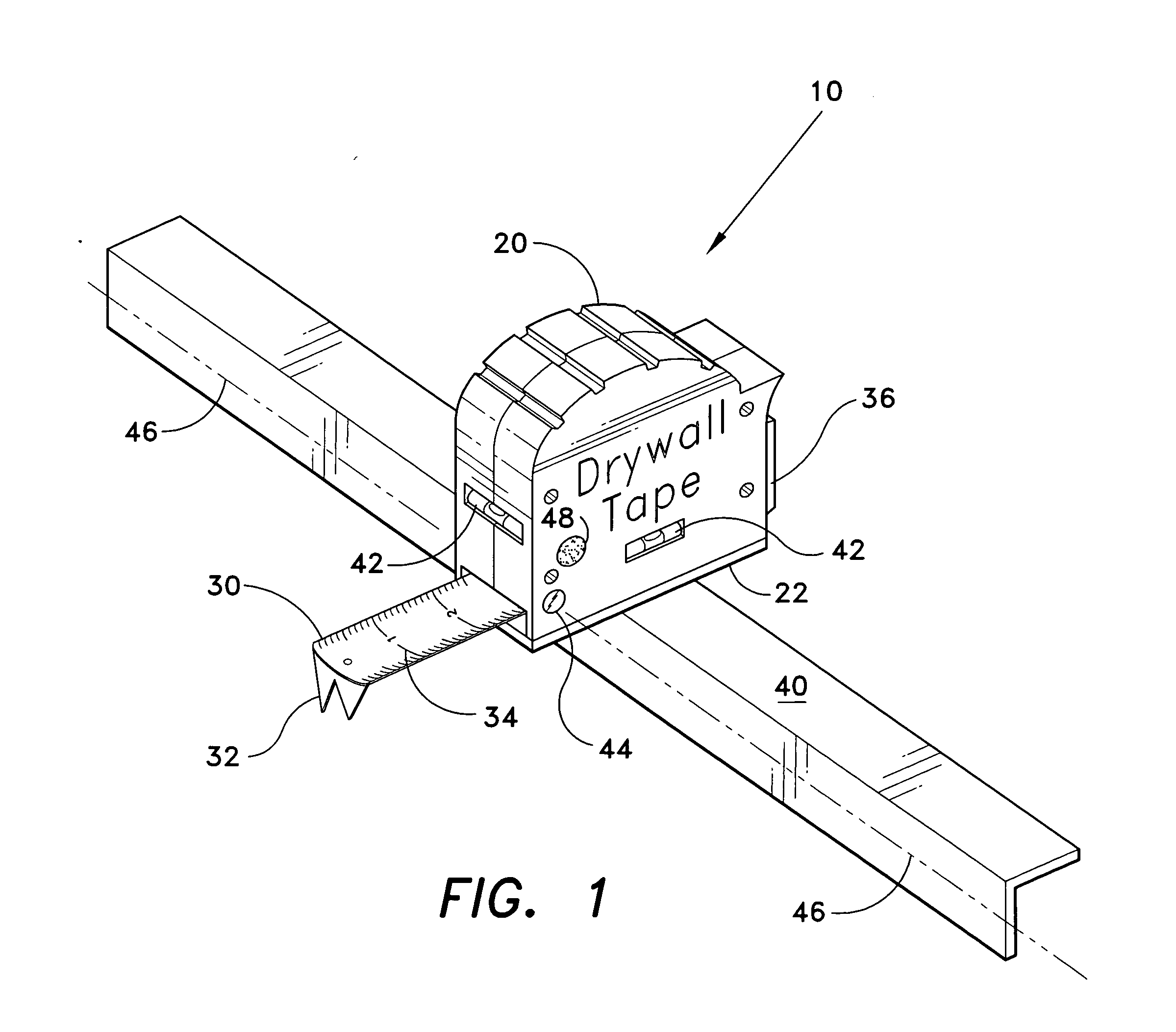
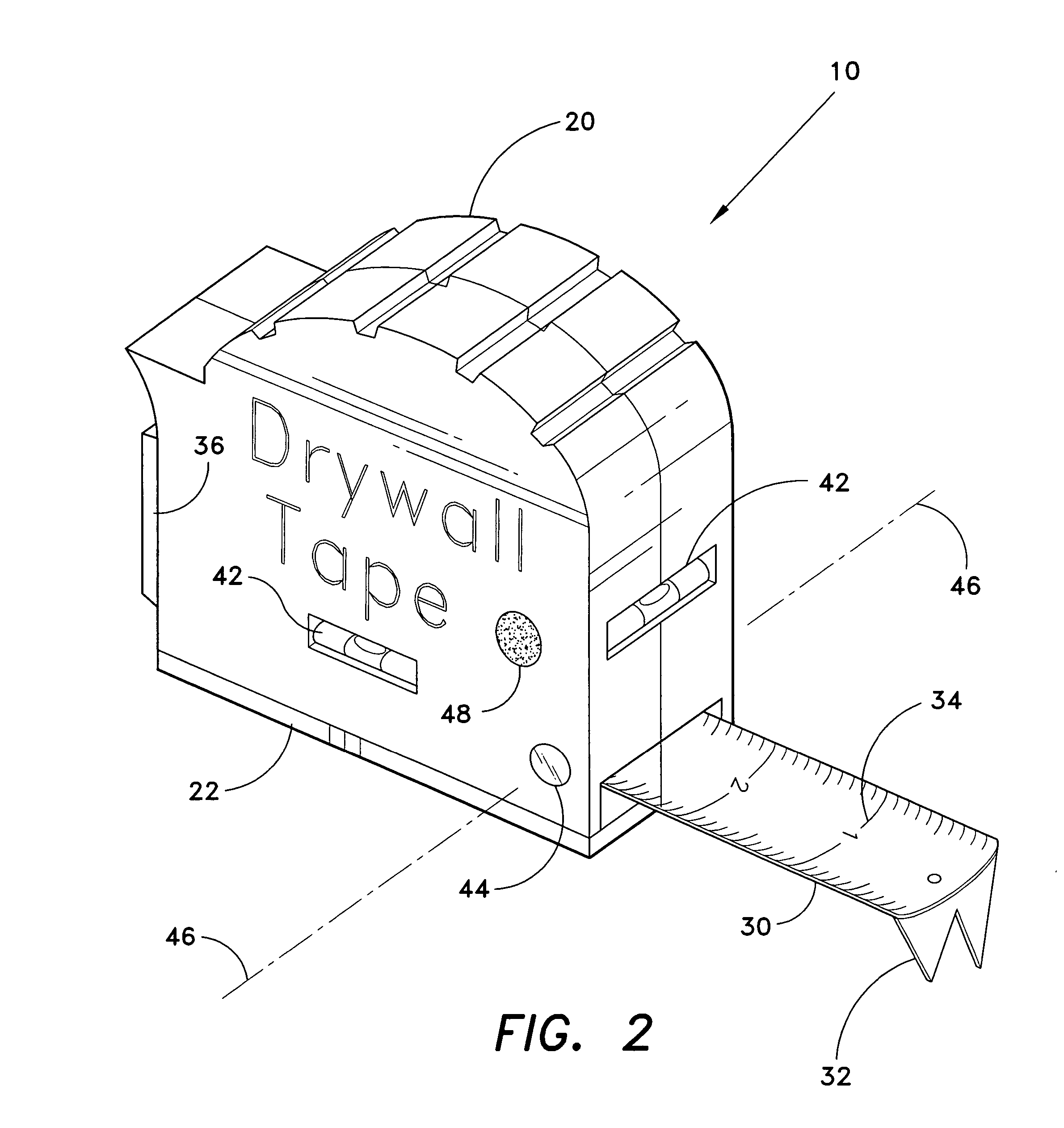
[0025] The present invention is a drywall measuring tape, designated generally as 10 in the drawings. Referring to FIGS. 1-3, the drywall measuring tape 10 comprises a housing 20 that contains a measuring tape 30. The measuring tape 30 is a conventional elongated flexible rule blade, disposed to be extended from and rewound into the housing 20 by a conventional spring reel mechanism. The housing 20 has a flat base 22. The measuring tape 30 extends from the housing adjacent to the base 22, and is extendable in line with, and in a plane roughly parallel to, the plane of the base 22.

[0026] The surface of the measuring tape 30 bears visual indicia 34 of the length of the extended tape relative to a measuring reference point of the drywall measuring tape 10. An end piece 32 is disposed on the end of the measuring tape 30. The end piece 32 functions to prevent the measuring tape 30 from being rewound into the housing 20. Additionally, the end piece 32 is useful, as with conventional meas...


PUM


Abstract

The drywall measuring tape is a tape measure extendably contained within a housing, including a laser light source, such as a laser diode, located on each side of the housing. Each laser light source projects a focused light beam perpendicular to the extended tape measure, and in a plane parallel to the housing base. Thus, when the tape measure is extended across a wall with the housing base flush against the wall, one of the laser light sources projects a reference spot onto the ceiling, while the other projects onto the floor. This allows a measurement to be taken horizontally across a wall in reference to a point on the ceiling or floor. Additionally, the drywall measuring tape includes a T-square bracket on the housing base, disposed so that the drywall measuring tape can be quickly aligned with a surface edge for measurement perpendicular to the surface edge.

Description

CROSS-REFERENCE TO RELATED APPLICATION [0001] This application claims the benefit of U.S. Provisional Patent Application Ser. No. 60 / 494,560, filed Aug. 13, 2003.BACKGROUND OF THE INVENTION [0002] 1. Field of the Invention [0003] The present invention relates to measuring tapes and, more specifically to a drywall measuring tape having a T-square bracket for aligning the drywall measuring tape along an edge of a drywall sheet, and having a pair of laser light sources projecting laser light beams perpendicularly to the extended measuring tape to facilitate taking measurements relative to a remote surface. [0004] 2. Description of the Related Art [0005] Measuring tapes are well known and widely used in countless situations where length or distance measurements are needed quickly and accurately. In construction, measuring tapes are essential to bring an architect's vision to life from a blueprint, translating written dimensions into the correct placement and sizing of raw construction m...

Claims


Application Information

Patent Timeline
Patent Type & Authority Applications(United States)
IPC IPC(8): G01B3/10G01C9/26
CPCG01B3/1061G01B3/1084G01C9/26G01B2003/1092G01B2003/1089G01B3/1089G01B3/1092
Inventor CONNOR, MICHAEL L.
Owner CONNOR MICHAEL L
Features
  • Generate Ideas
  • Intellectual Property
  • Life Sciences
  • Materials
  • Tech Scout
  • Unparalleled Data Quality
  • Higher Quality Content
  • 60% Fewer Hallucinations
Learn More