Enhanced pumped storage power system

a technology of pumped storage and power system, which is applied in the direction of renewable energy generation, fluid couplings, greenhouse gas reduction, etc., can solve the problems of adding significantly to the implementation cost, and achieve the effect of effectively conserving natural resources

Inactive Publication Date: 2005-02-17
DAVIS LESTER
View PDF15 Cites 53 Cited by
  • Summary
  • Abstract
  • Description
  • Claims
  • Application Information

AI Technical Summary

Benefits of technology

[0054] Finally, it is an object of the present invention to provide a system...

Problems solved by technology

An additional drawback associated with such a system is the need to dam a portion of th...

Method used


Image

  • Enhanced pumped storage power system
  • Enhanced pumped storage power system

Examples


second embodiment

[0071] More particularly, in the second embodiment, the traditional-type water tower contains a previously-determined quantity of water at an elevation common for town or municipal water supply. The capacity of a town water tower is sufficient for the purposes of the invention, and the appearance of the water tower is familiar to all area residents. Because the present invention teaches the usage of a system that works effectively without very high elevation, the height of a standard water tower is also sufficient to provide enough downward pressure to generate the requisite degree of electrical power.

[0072] Although the usage of a water tower as the upper reservoir inherently provides less power than the preferred embodiment described above, this second embodiment is still effective for small to medium sized geographic areas and regions of lower or average population. Importantly, the water towers are predominantly previously-existing, allowing for conversion to the power system of...

third embodiment

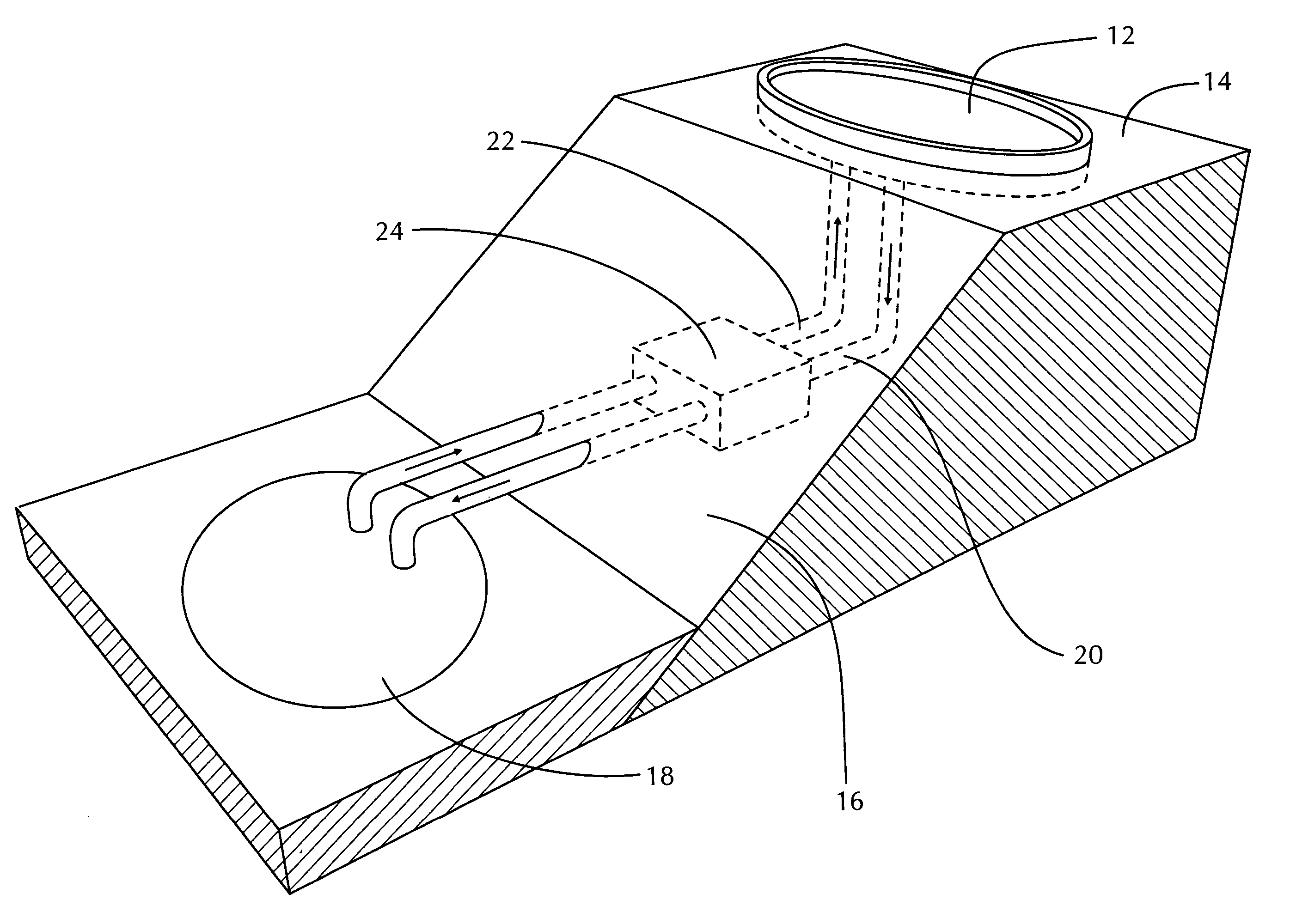
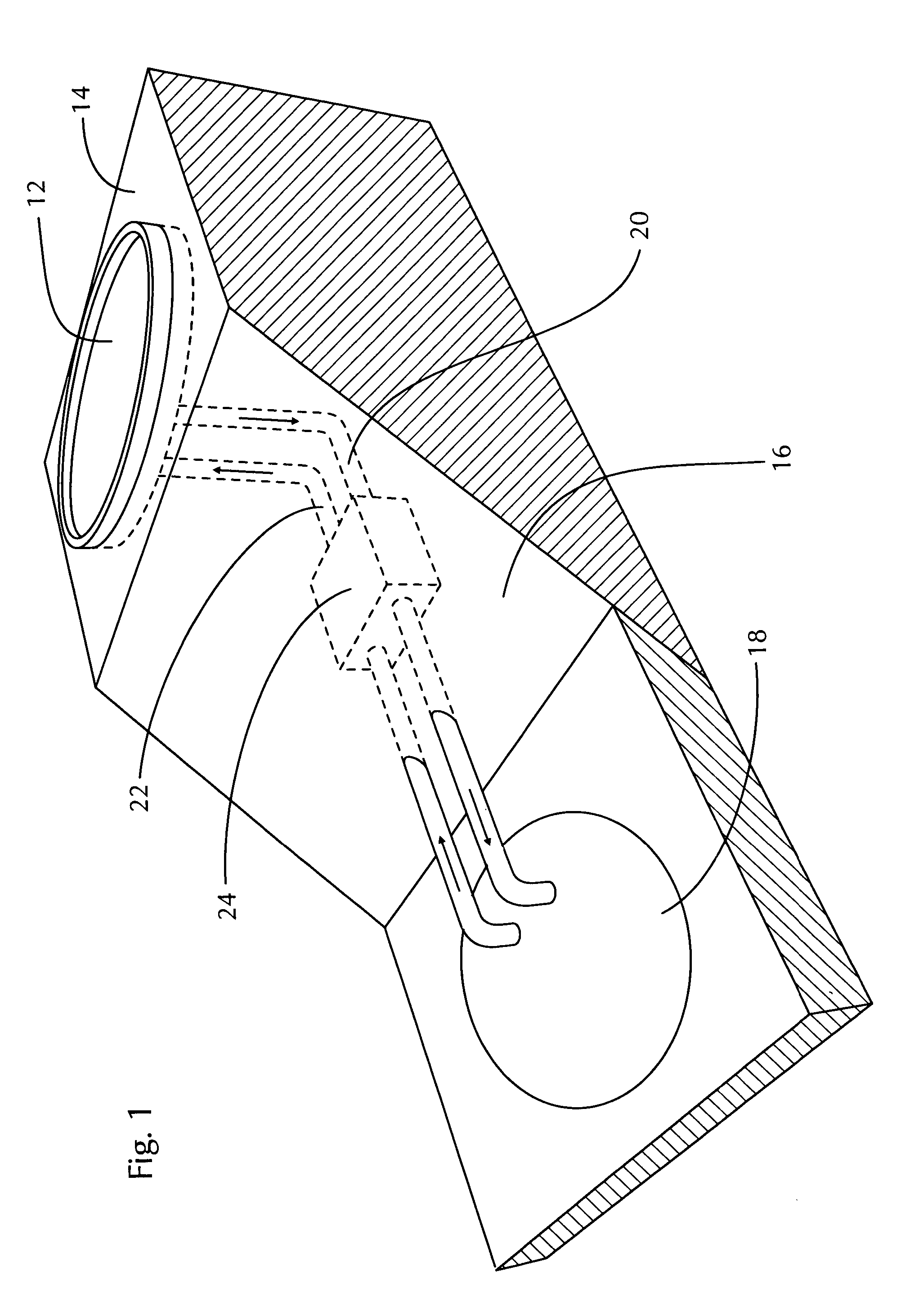
[0074] Next, in the present invention, the system utilizes a first reservoir upon generally flat land in conjunction with a relatively large concavity in which the second reservoir sits. This comprises the difference in elevation required to generate strong gravitational forces between the dual reservoirs to generate electrical power, and all other concepts and theories associated with the above-described embodiments are incorporated therein.

[0075] More particularly, in this third embodiment, the first reservoir is actually located at ground level adjacent a large concavity or crater in the landscape. The second, lower reservoir is located within this concavity, working much in the manner as described above with the primary embodiment, with the sizes of the two reservoirs consistent with those described above.

[0076] As such, the third embodiment importantly allows for usage of the concepts and benefits of the present invention absent true elevation above the landscape of the first ...


PUM


Abstract

An enhanced pumped storage power system. More particularly, the invention is a regenerative power system that utilizes the gravitational forces of downward movement of large quantities of water to convert same to electrical energy. In the preferred mode of implementation, the system utilizes a man-made lake at a first level of elevation. Though higher altitudes can be effective, the lake need only be approximately twenty to thirty feet in elevation. The lake, which may exceed one hundred acres in size, may be elevated above and adjacent a natural body of water, such as seawater at a coastline. As such, sandy terrain associated with the region facilitates initial construction of the system. An underground generator is utilized for the power conversion and pumping of the water back to the upper reservoir during times of low energy demand, allowing for significant noise reduction. Importantly, the system of the present invention may be utilized to provide significant levels of power to serve relatively large geographic areas during times of peak energy demand, when other sources of power are more expensive and subject to power outages. Finally, it should be noted that the components of the system are aesthetically-pleasing in nature, allowing the system to be effectively utilized in a residential area.

Description

BACKGROUND OF THE INVENTION [0001] 1. Field of the Invention [0002] The present invention is an enhanced pumped storage power system. More particularly, the invention is a regenerative power system that utilizes the gravitational forces of downward movement of large quantities of water to convert same to electrical energy. [0003] In the preferred mode of implementation, the system utilizes a man-made lake at a first level of elevation. Though higher altitudes can be effective, the lake need only be approximately twenty to thirty feet in elevation. The lake, which may exceed one hundred acres in size, may be elevated above and adjacent a natural body of water, such as seawater at a coastline. As such, sandy terrain associated with the region facilitates initial construction of the system. An underground generator is utilized for the power conversion and pumping of the water back to the upper reservoir during times of low energy demand, allowing for significant noise reduction. Import...

Claims


Application Information

Patent Timeline
IPC IPC(8): E02B9/00F03B3/10F03B13/08
CPCE02B9/00F03B3/103F03B13/06Y02E60/17Y02E10/22Y02E10/223Y02E10/46F03B13/08Y02E10/20Y02E60/16
Inventor DAVIS, LESTER
Owner DAVIS LESTER
Why Eureka
Try Eureka