Outdoor unit for air conditioner

a technology for outdoor units and air conditioners, applied in the field of outdoor units for air conditioners, can solve the problems of reducing heat exchange efficiency, and discharging condensed water, and achieve the effect of preventing condensed water from freezing and easy discharg

a technology for outdoor units and air conditioners, applied in the field of outdoor units for air conditioners, can solve the problems of reducing heat exchange efficiency, and discharging condensed water, and achieve the effect of preventing condensed water from freezing and easy discharg

US20050034471A1Inactive Publication Date: 2005-02-17SAMSUNG ELECTRONICS CO LTD

Image

  • Outdoor unit for air conditioner
  • Outdoor unit for air conditioner
  • Outdoor unit for air conditioner

Examples


Embodiment Construction

[0024] Reference will now be made in detail to embodiments of the present invention, examples of which are illustrated in the accompanying drawings, wherein like reference numerals refer to the like elements throughout. The description below explains the present invention by referring to the figures.

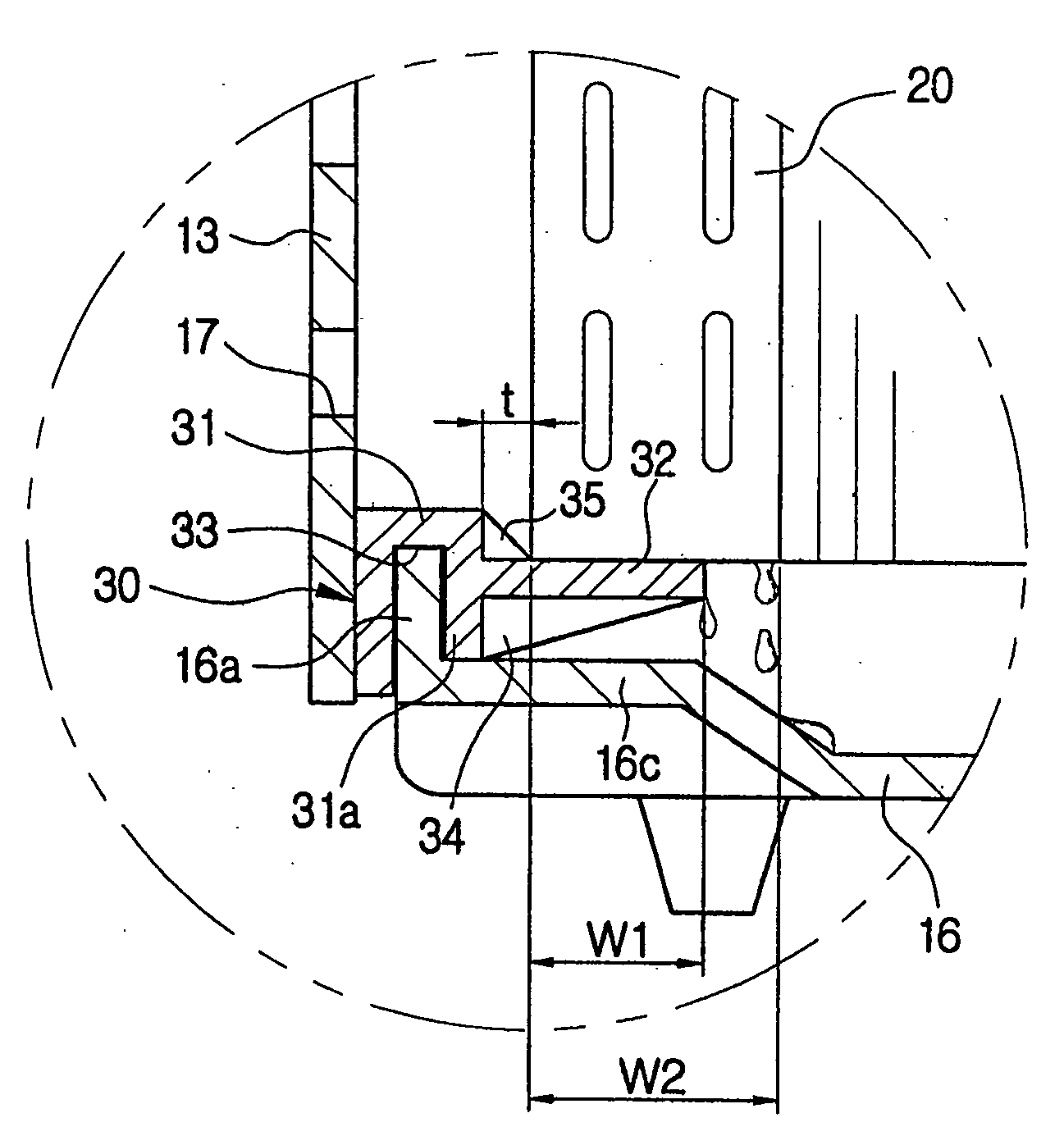
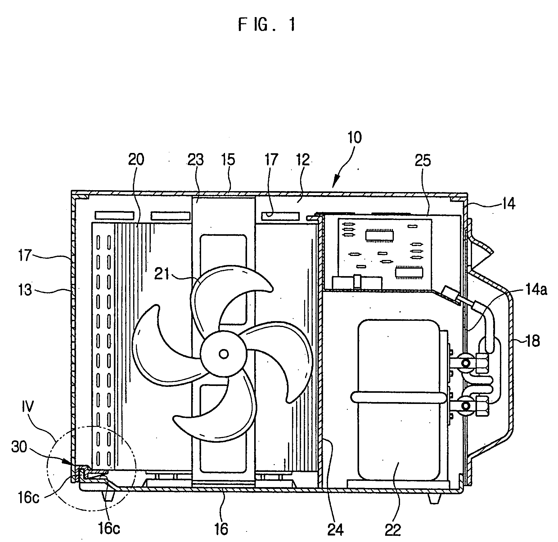
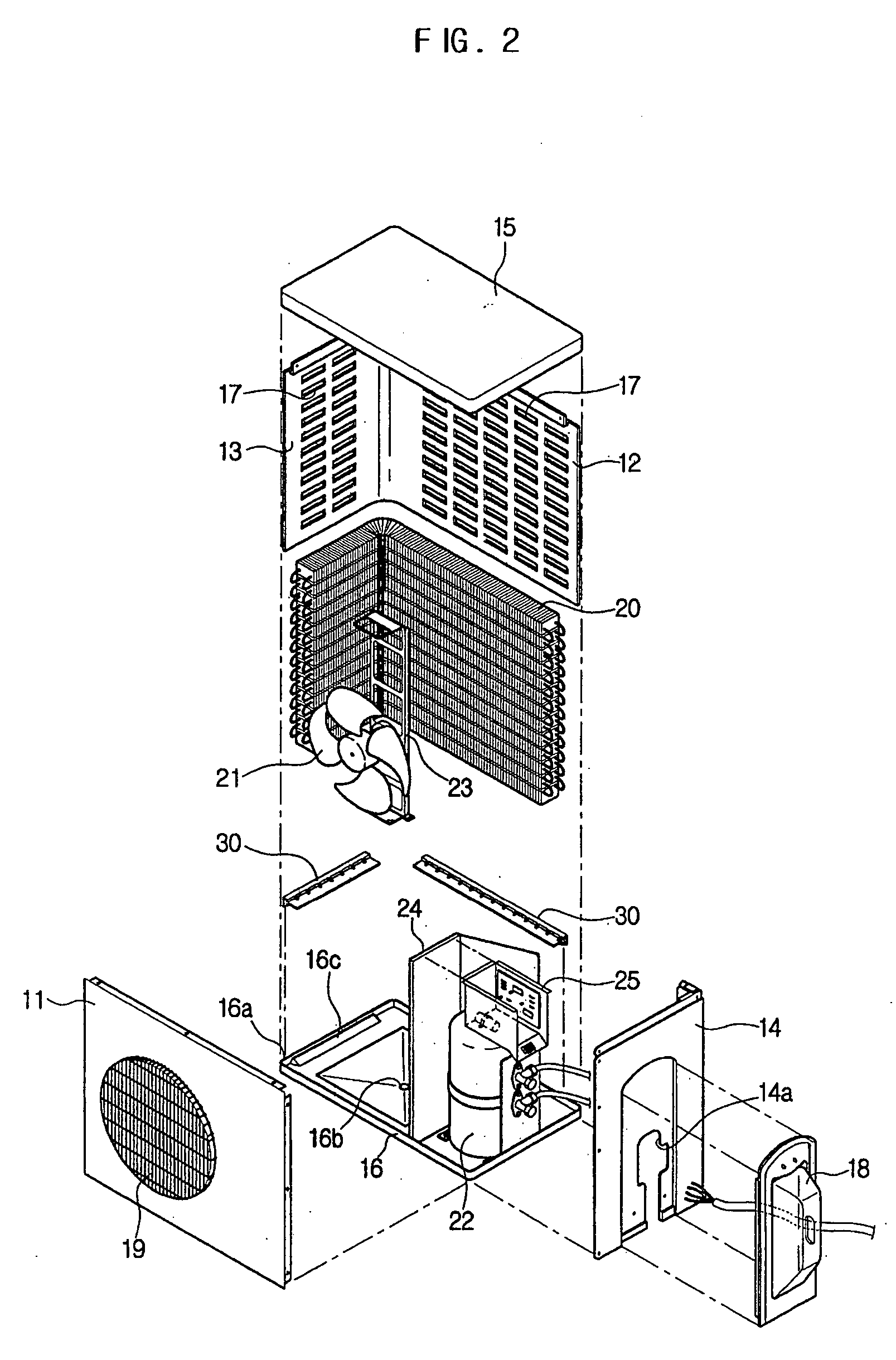
[0025] As shown in FIGS. 1 and 2, an outdoor unit for an air conditioner according to an embodiment of the present invention includes a box-shaped cabinet 10 having a front panel 11, a rear panel 12, both side panels 13 and 14, a top panel 15, and a bottom panel 16, which are coupled to one another. The rear panel 12 and a side panel 13 of the cabinet 10 are manufactured by bending an integral plate, and include suction holes 17. The other side panel 14 includes an opening 14a to permit electric wires for transferring power and a refrigerant piping to pass therethrough. The opening 14a is covered with a cover member 18. The front panel 11 includes a discharge port 19 to allow air, which...


PUM


Abstract

An outdoor unit for an air conditioner allows condensed water generated from an outdoor heat exchanger to be easily discharged, and prevents coldness from the outdoor heat exchanger from being transmitted to a bottom of the outdoor unit, thus preventing freezing of the condensed water on the bottom. The outdoor unit includes a cabinet having a bottom panel, an outdoor heat exchanger installed in the cabinet, and a support member made of heat insulating material supporting the outdoor heat exchanger with a spacing between a lower end of the outdoor heat exchanger and the bottom panel of the cabinet, to prevent condensed water generated from the outdoor heat exchanger from freezing.

Description

CROSS-REFERENCE TO RELATED APPLICATIONS [0001] This application claims the benefit of Korean Patent Application No. 2003-56358, filed Aug. 14, 2003 in the Korean Intellectual Property Office, the disclosure of which is incorporated herein by reference. BACKGROUND OF THE INVENTION [0002] 1. Field of the Invention [0003] The present invention relates to an air conditioner, and more particularly, to an outdoor unit for an air conditioner, which is designed to prevent condensed water from forming on a heat exchanger. [0004] 2. Description of the Related Art [0005] Generally, a separated-type air conditioner includes an indoor unit installed inside a building and an outdoor unit installed outside a building, in which the indoor unit and the outdoor unit are connected to each other via refrigerant piping. The indoor unit usually includes an indoor heat exchanger to generate coldness by heat exchange, and a circulating fan to circulate air in a room. The outdoor unit includes a compressor,...

Claims


Application Information

Patent Timeline
17 Feb 2005
Publication
US20050034471A1
IPC
F24F1/00; F24F13/22
CPC
F24F1/16; F24F1/36; F24F1/48; F28F2265/22; F28F17/005; F28F2270/00; F28F2265/14; F24F13/222
Inventors
SHIN, SANG HO