
Electrical capacitance sapphire diaphragm pressure sensor and a method of fabricating the same

Inactive Publication Date: 2005-02-17
TEM TECH LAB
View PDF3 Cites 6 Cited by
  • Summary
  • Abstract
  • Description
  • Claims
  • Application Information

AI Technical Summary

Benefits of technology

[0015] The object of the present invention is to provide a highly accurate electrical capacitance sapphire diaphragm pressure sensor capable of detecting a pressure without being affected by temperature drift that occurs when a pressure transfer coefficient changes with variations of a temperature of a fluid whose pressure is to be measured, and a method of manufacturing the same.
[0030] According to the present invention, a sapphire diaphragm, which is formed as a pressure-sensing element, can be readily and yet firmly secured on a metal base. Therefore, the present invention can provide a highly accurate electrical capacitance diaphragm pressure sensor capable of reducing temperature drift, taking advantage of the characteristics of a sapphire diaphragm.
[0031] Further, a pressure sensor of the present invention has an extremely simple configuration for firmly securing a sapphire diaphragm on a metal base and therefore, it is easy to manufacture an electrical capacitance diaphragm pressure sensor in accordance with the present invention.
[0032] Still further, the present invention can provide a diaphragm pressure sensor having a simple configuration using a sapphire diaphragm capable of reducing temperature drift and therefore, a pressure sensor of the present invention does not need a temperature compensation circuit in its pressure sensing circuit, and the cost of manufacturing the present diaphragm pressure sensor is therefore substantially reduced.

Problems solved by technology

In a conventional diaphragm pressure sensor such as that described above, a pressure transfer coefficient varies according to a temperature of a fluid whose pressure is to be measured, and instability such as temperature drift and the like is thereby caused, and as a result, measurement accuracy is significantly compromised.
It is known that a leading cause of temperature drift in a diaphragm pressure sensor is a thermal expansion / contraction coefficient of a diaphragm material.
However, it is extremely difficult to tightly secure a sapphire diaphragm on a metal base for holding the diaphragm during the process of manufacturing of a sapphire diaphragm pressure sensor, and practical implementation of a sapphire diaphragm pressure sensor is therefore difficult.
According to this method, however, application of an insufficient amount of adhesive, deterioration of applied adhesive, weak binding between molecules or the like may result in a diaphragm becoming detached from the metal base.
Additionally, the adhesive employed may restrict types of medium whose pressure the sensor can measure.
However, since a thin layer of metal also covers a surface of a diaphragm on which a pressure acts, thermal expansion of the thin metal layer covering the diaphragm causes temperature drift.
However, thermal expansion of the housing element as well as the fluid causes temperature drift.
According to this method, however, a diaphragm cannot be secured in an entirely stable manner, and a leakage of a medium whose pressure is to be measured is thereby caused.
Further, since a medium whose pressure is to be measured tightens the O-ring when the pressure detection begins, detection accuracy drops due to initial deflection of the diaphragm.
Still further, media whose pressure can be measured by a sensor are restricted according to the material of which an O-ring is made, and a medium whose pressure is to be measured might leak if a back-up ring is not properly installed.

Method used


Image

  • Electrical capacitance sapphire diaphragm pressure sensor and a method of fabricating the same
  • Electrical capacitance sapphire diaphragm pressure sensor and a method of fabricating the same
  • Electrical capacitance sapphire diaphragm pressure sensor and a method of fabricating the same

Examples


Embodiment Construction

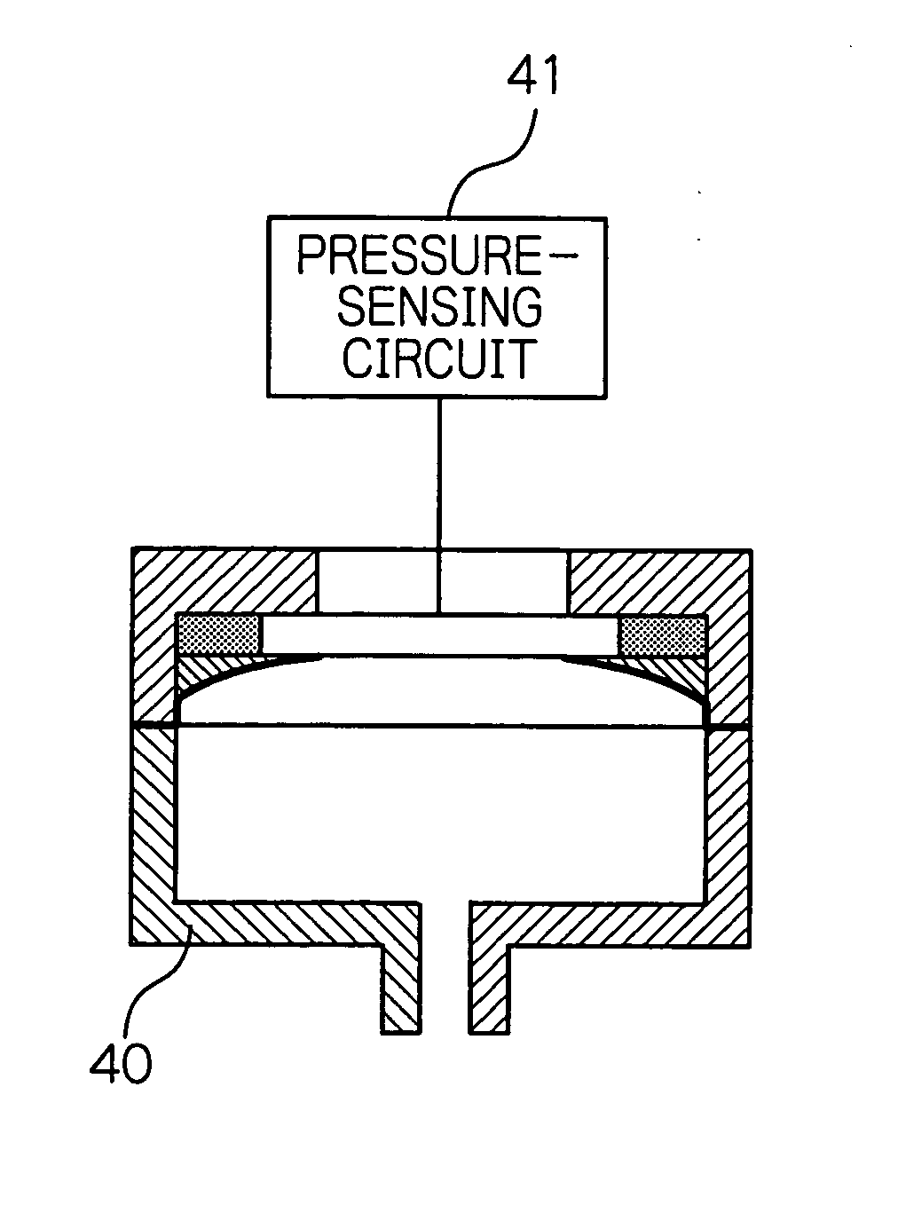
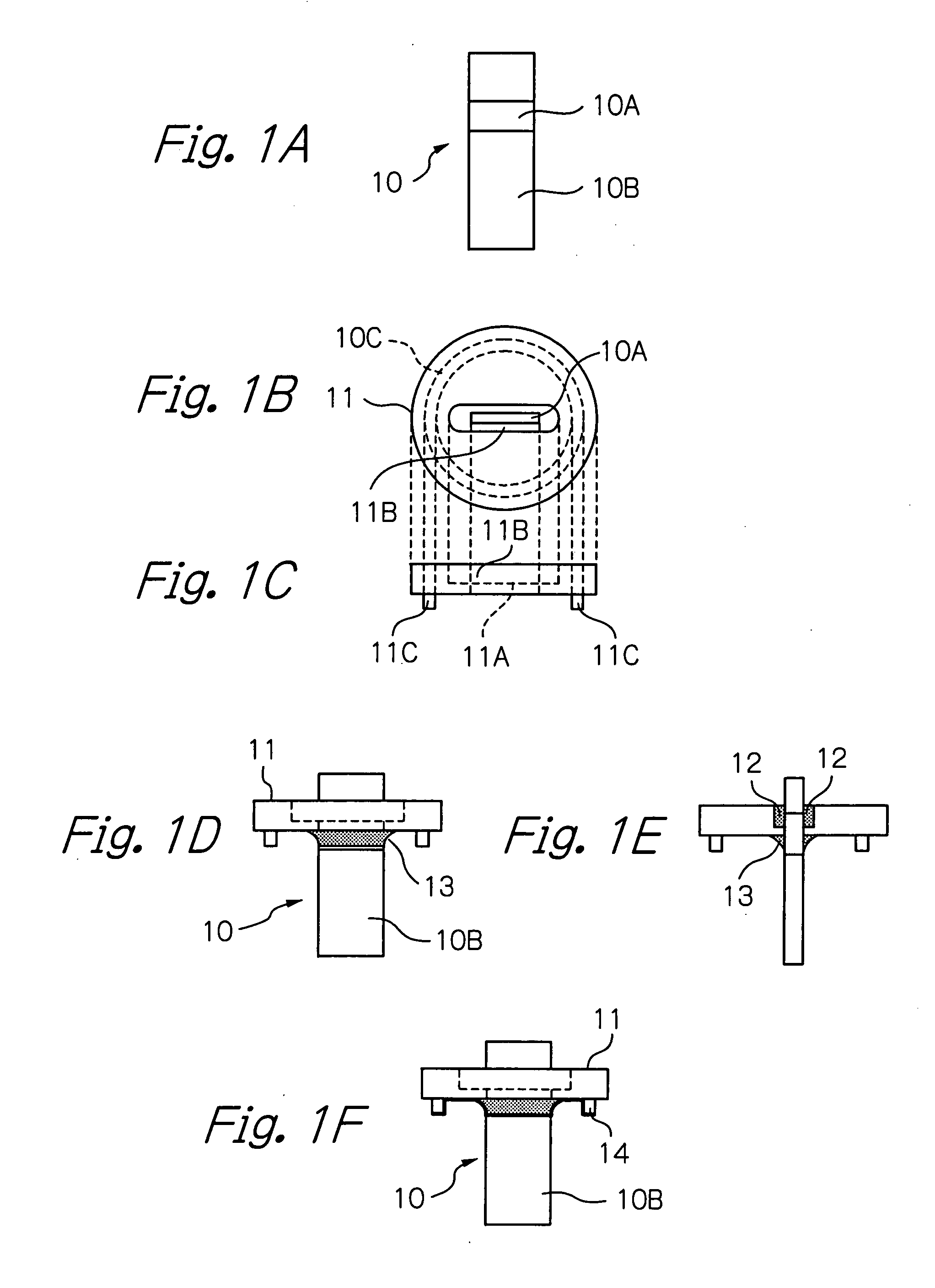
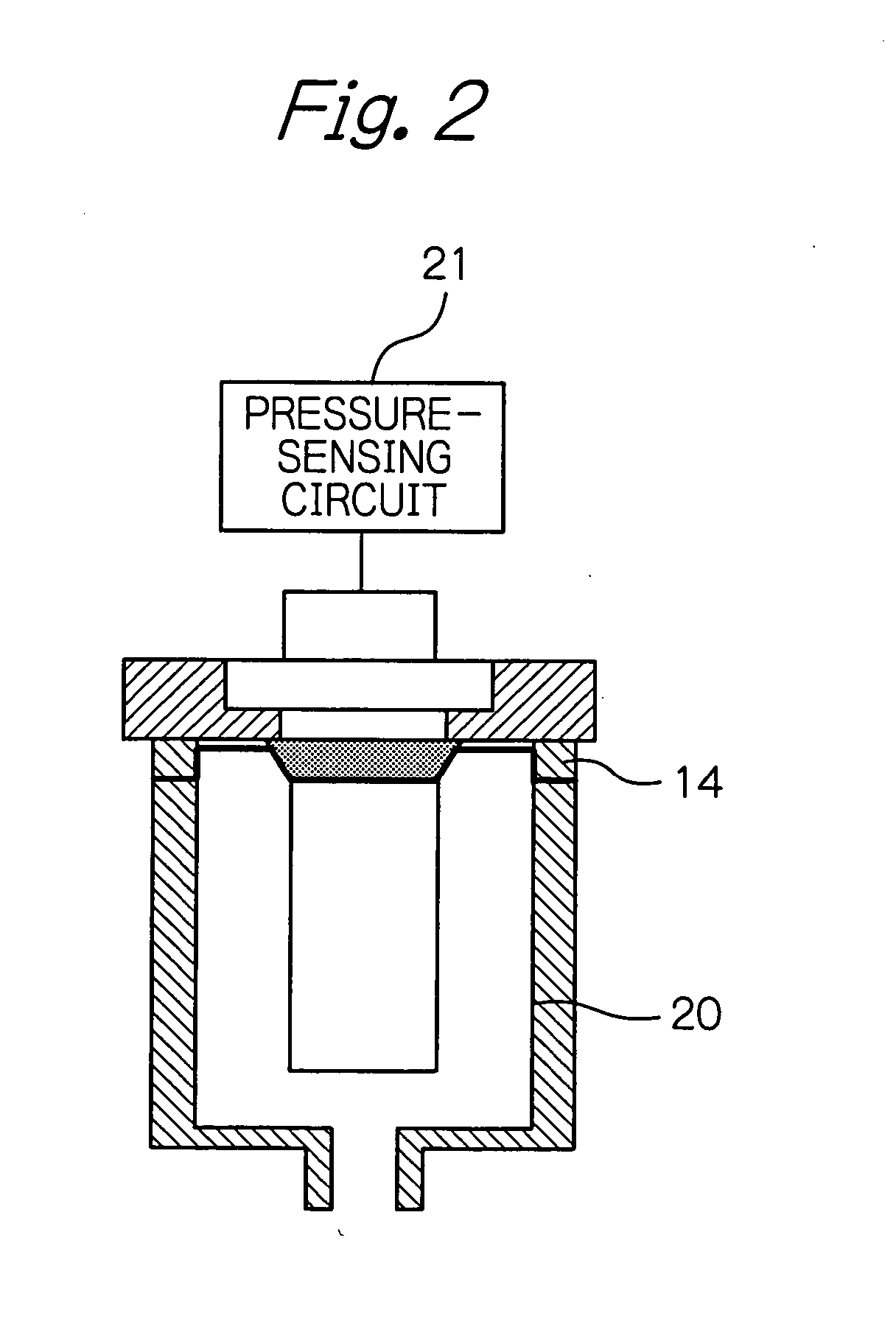
[0037]FIG. 1 is an illustration of the strip-shaped pressure-sensing element (sapphire plate) 10 constituting a main portion of a capacitance sapphire diaphragm pressure sensor. FIG. 1 also illustrates a basic manufacturing process of the pressure sensor.

[0038] Although FIG. 1A portrays the pressure-sensing element 10 simply as a strip-shaped member and, for the sake of simplicity, does not show its details, the element actually consists of two strip-shaped sapphire diaphragms arranged in opposing relation with a spacer between them, and deposition electrodes formed on opposing surfaces of the diaphragms, and the two strip-shaped sapphire diaphragms are assembled in an integral fashion to constitute a single unit. The opposing deposition electrodes are respectively connected through a lead wire to an electrode output terminal formed at the end of the pressure-sensing element 10 to output a detected signal.

[0039] The surface of the integrally structured sapphire diaphragm, with the...


PUM


Abstract

There is provided a highly accurate electrical capacitance diaphragm pressure sensor capable of reducing temperature drift that arises when a pressure-travel coefficient changes with temperature variations of a fluid whose pressure is sensed. A sapphire diaphragm pressure sensor, in which sapphire diaphragms are arranged in opposing relation, comprises a pressure sensing element (10, 30) having a pressure receiving part (10A, 30A) with a deposition electrode formed on each of the opposing faces of sapphire diaphragms which are provided in opposing relation to each other and a securing part with a metal deposited on a part of each of the surfaces of the sapphire diaphragms, and further comprises a metal base (11, 31) for securing the pressure sensing element at the securing part of the pressure sensing element, a conductive sealing agent (13, 33) for sealing a gap between the securing part on which a metal is deposited and said metal base, and a nickel protective layer (14, 34) for protecting at least said conductive sealing agent from a medium whose pressure is to be measured.

Description

BACKGROUND OF THE INVENTION [0001] The present invention is directed to a pressure sensor and a method of fabricating the same, and in particular to an electrical capacitance sapphire diaphragm pressure sensor for sensing a fluid pressure in, for example, a container for chemicals, a pipe for chemicals or the like, and a method of fabricating the same. [0002] Conventional pressure sensors for sensing a fluid pressure in a container for chemicals, a pipe for chemicals or the like, are provided with a diaphragm which acts as a pressure-sensing element, whereby deflection of the diaphragm in response to an applied pressure is converted into an electric signal, to thereby sense a pressure. [0003] Japanese Patent Application No. 2002-130442 discloses an example of such a diaphragm pressure sensor in the invention titled “Electrical capacitance diaphragm pressure sensor”. [0004] Such a diaphragm pressure sensor normally comprises: a pressure-sensing element provided with a pressure receiv...

Claims


Application Information

Patent Timeline
IPC IPC(8): G01L9/00G01L9/12
CPCG01L9/0075
Inventor AIZAWA, MITSUYOSHI
Owner TEM TECH LAB
Learn More