Exhalation valves

a technology of exhalation valve and valve body, which is applied in the field of exhalation valve, can solve the problems of high energy consumption, high cost of solutions, and high energy consumption of patients, and achieve the effect of reducing the risk of lung deformation

Active Publication Date: 2005-02-17
INTERSURGICAL AG
View PDF32 Cites 45 Cited by
  • Summary
  • Abstract
  • Description
  • Claims
  • Application Information

AI Technical Summary

Benefits of technology

[0011] According to the invention, there is provided an exhalation valve for use with an exhalation port of a respiratory circuit, the exhalation valve comprising a hermetically sealed gas chamber, a gas inlet for supplying gas to the gas chamber, and a membrane of flexible material defining at least part of a wall of the gas chamber, the membrane being situated, in use, adjacent to the exhalation port, and the membrane being deformable by a change in the pressure differential between t...

Problems solved by technology

This is because complete deflation, and subsequent reflation, of the patient's lungs requires a significant amount of the patient's energy.
However, a problem with exhalation valves of this type is that a certain amount of pressure, the “deforming pr...

Method used


Image

  • Exhalation valves
  • Exhalation valves
  • Exhalation valves

Examples


Embodiment Construction

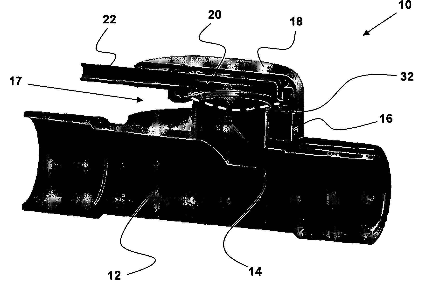
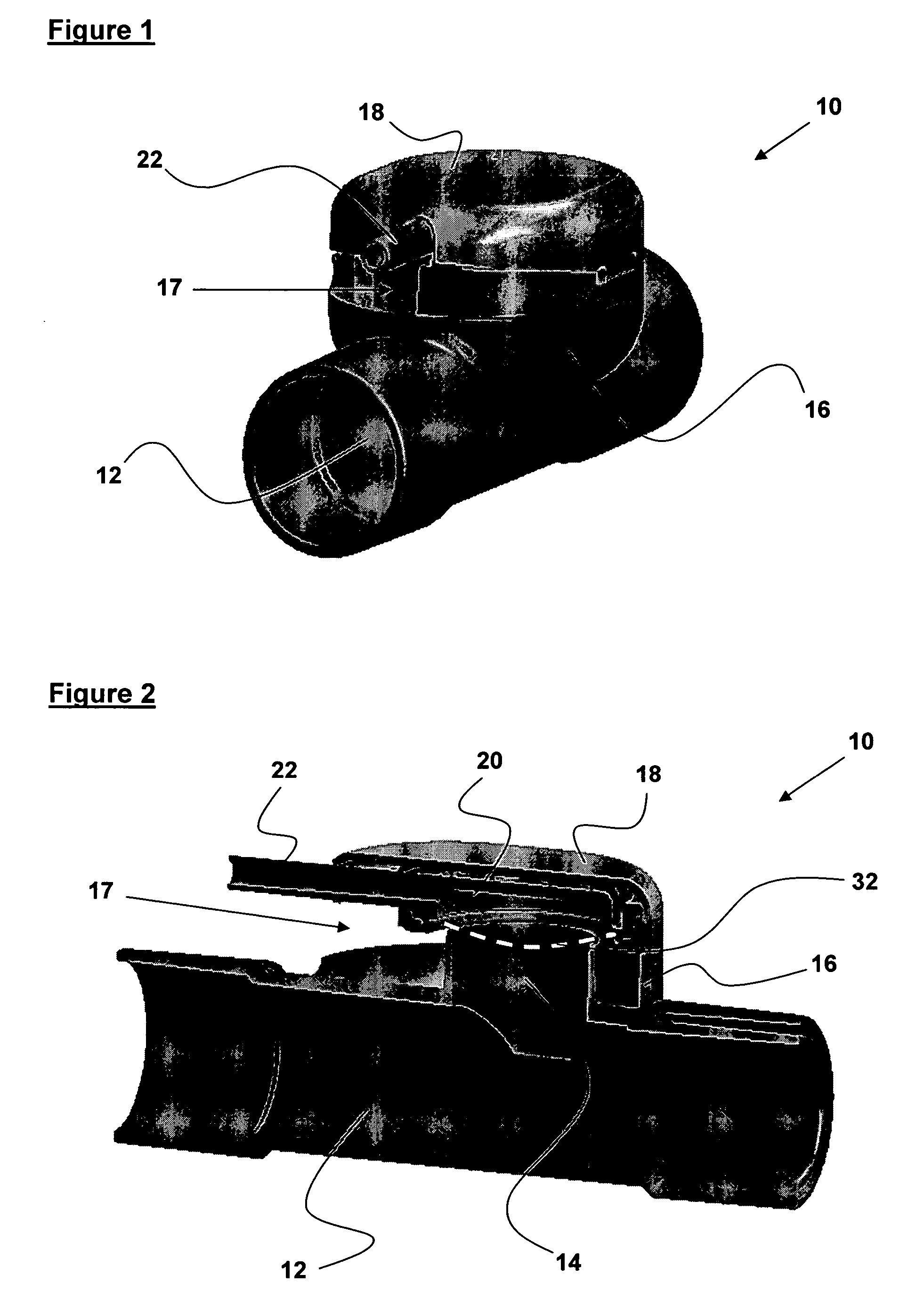
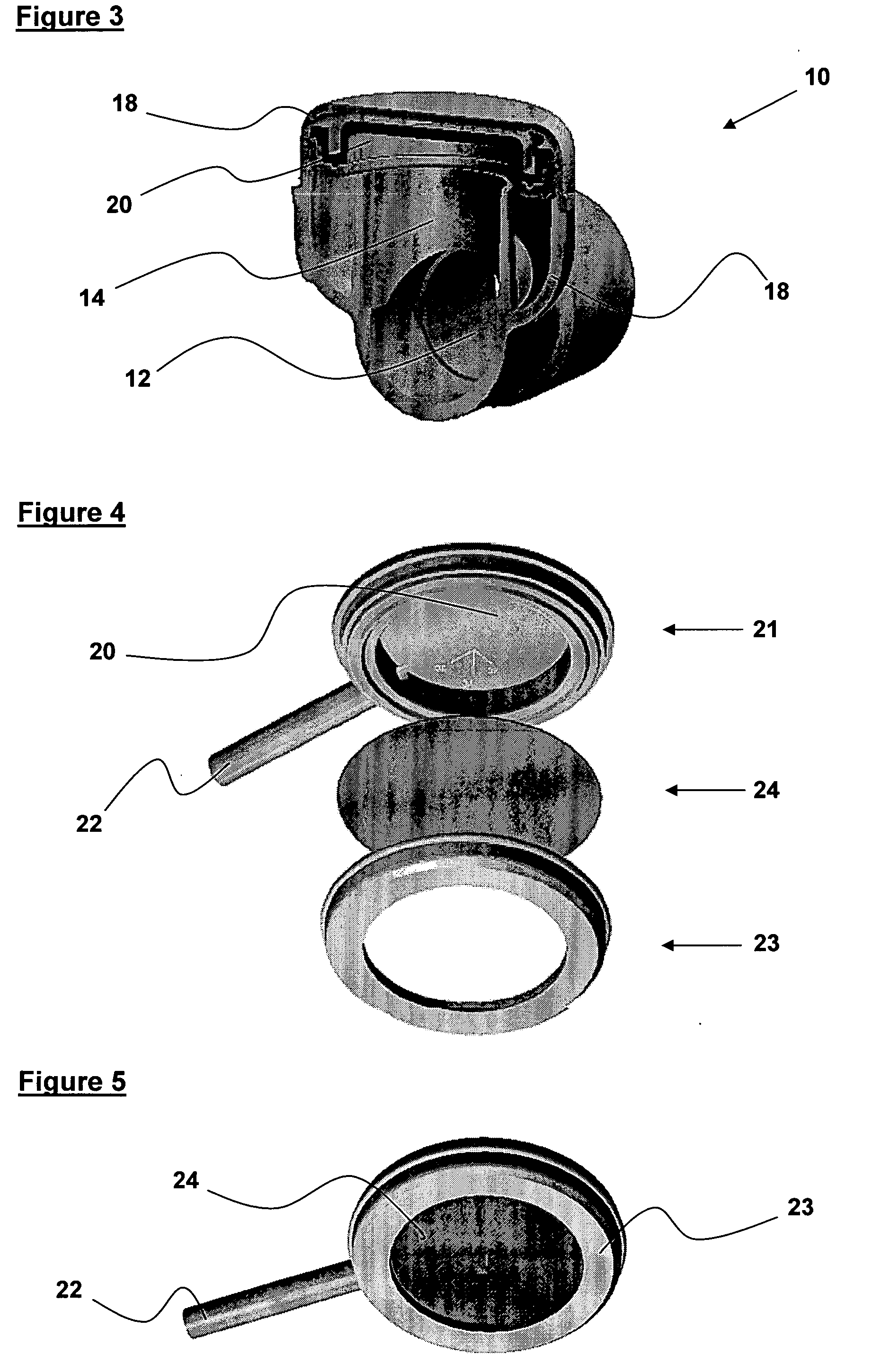
[0040]FIGS. 1, 2 and 3 show an exhalation valve according to the invention which is generally designated 10. The exhalation valve 10 comprises a respiratory passageway 12, an exhalation port 14, a lower housing 16, an upper housing 18, a gas chamber 20, a gas inlet pipe 22 and a membrane of flexible material 24 (the membrane 24 is not visible in FIG. 1, and is not shown in FIG. 2 or 3, but its location during use is indicated by a broken line 32 in FIG. 2).

[0041] The respiratory passageway 12 is adapted at either end to connect to a respiratory circuit. The exhalation port 14 branches perpendicularly from a central portion of the respiratory passageway 12 and terminates at a circular opening. The lower housing 16 has the form of an upright bowl and extends upwardly, around the exhalation port 14, from the upper surface of the respiratory passageway 12. The respiratory passageway 12, the exhalation port 14 and the lower housing 16 are integrally formed as a single component of plast...


PUM


Abstract

An exhalation valve (10) is disclosed for use with an exhalation port (14) of a respiratory circuit. The exhalation valve comprises a hermetically sealed gas chamber (20,120), a gas inlet (22,122) for supplying gas to the gas chamber, and a membrane (24,124) of flexible material that defines at least part of a wall of the gas chamber. The membrane is deformable by a change in the pressure differential between the gas within the gas chamber and the gas within the exhalation port between an inoperative configuration and an operative configuration in which the membrane restricts the flow of gas from the exhalation port to a greater extent than in said inoperative configuration. The membrane is inherently planar but is mounted within the exhalation valve such that deformation of the membrane to its operative configuration occurs substantially without increase of the surface area of the membrane.

Description

[0001] This application claims the priority benefit of UK patent application 0317801.9, filed Jul. 30, 2003, which is hereby incorporated by reference in its entirety. BACKGROUND OF THE INVENTION [0002] This invention relates to exhalation valves used where Patient End Expiratory Pressure (PEEP) is applied to an artificial respiratory circuit, and in particular to exhalation valves used where the applied Patient End Expiratory Pressure is adjustable. [0003] When a patient is unable to breathe unaided, or requires assistance with breathing, the patient is usually connected to an artificial respiratory circuit including a ventilator programmed by a clinician to deliver an appropriate volume of air, or an air / oxygen mixture, to the patient. In such a respiratory circuit, it is desirable to prevent the patient from exhaling fully, and therefore the patient's lungs from deflating fully. This is because complete deflation, and subsequent reflation, of the patient's lungs requires a signif...

Claims


Application Information

Patent Timeline
IPC IPC(8): A61M16/20
CPCA61M16/20A61M16/206A61M16/205A62B9/02
Inventor PITTAWAY, ALAN KENNETHJASSELL, SURINDERJIT KUMAR
Owner INTERSURGICAL AG
Why Eureka
Try Eureka