Connection arrangement to connect two flexible tanks of an aircraft

a flexible tank and connection arrangement technology, applied in the direction of transportation items, liquid handling, packaging goods types, etc., can solve the problems of difficult installation of such a plurality of tanks, and achieve the effect of convenient installation, simple setup and easy removal

Inactive Publication Date: 2005-02-17
AIRBUS HELICOPTERS DEUT GMBH
View PDF18 Cites 21 Cited by
  • Summary
  • Abstract
  • Description
  • Claims
  • Application Information

AI Technical Summary

Benefits of technology

[0004] An objective of the present invention is to provide a connection arrangement to connect two flexible tanks in aircraft which makes it possible to easily install and to easily remove at least one flexible tank while keeping the set-up simple and cost-effective.
[0006] The connection arrangement according to the invention to detachably connect two flexible tanks in aircraft makes it possible to greatly simplify the installation or removal of the flexible tanks. For this purpose, the connection arrangement according to the invention comprises a first tubular connecting element attached to the first tank, a second tubular connecting element attached to the second tank and a latching device. This latching device detachably connects the first and the second connecting elements to each other. Here, in the installed, that is to say, connected state of the tanks, fluid exchange takes place between the two flexible tanks via the first and the second connecting elements. Furthermore, the latching device is situated inside one of the two flexible tanks and it can be actuated from the outside of this flexible tank through the flexible tank. In other words, the latching device is actuated indirectly through the flexible tank, a process in which the latching device cannot be directly touched, but rather, the latching device can only be felt and actuated through the flexible jacket of the tank. Another advantage of the connection arrangement according to the invention between two tanks is that the installation space that is available for the tank can be fully utilized since it is not necessary to leave a gap between the two flexible tanks as is the case in the state of the art. Through the arrangement of the latching device inside one tank, two adjacent tanks can then be positioned as closely as possible next to each other.

Problems solved by technology

In particular, due to design-related space constraints, several small tanks that are connected to each other are often used instead of one large tank.
Due to the tight space available, it is frequently difficult to install such a plurality of tanks.

Method used


Image

  • Connection arrangement to connect two flexible tanks of an aircraft
  • Connection arrangement to connect two flexible tanks of an aircraft
  • Connection arrangement to connect two flexible tanks of an aircraft

Examples


Embodiment Construction

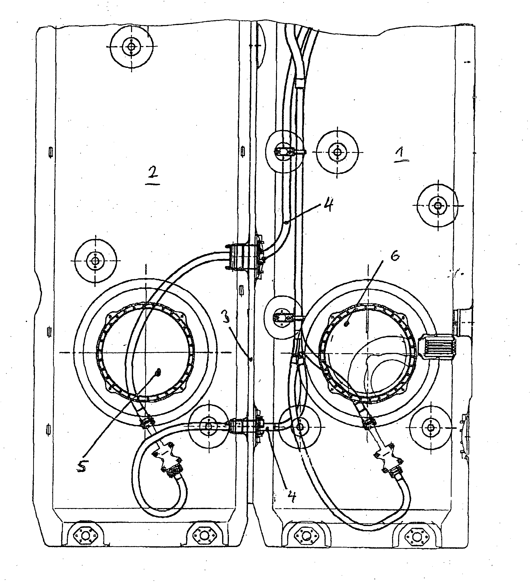
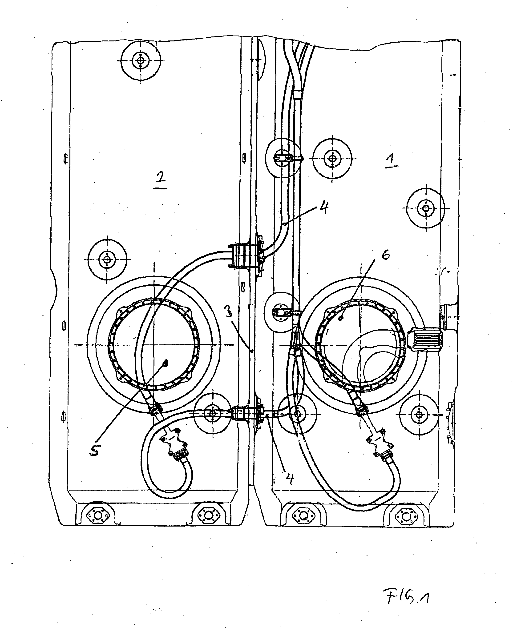
[0019] As can be seen in FIGS. 1 and 2, a first flexible tank 1 and a second flexible tank 2 for an aircraft are arranged next to each other. Here, both tanks 1, 2 are separated from each other by a rib 3. In their filled state, both flexible tanks 1, 2 lie against the rib 3. As depicted in FIG. 1, several fuel lines 4 as well as, in each case, closeable tank openings 5 and 6 are provided for each tank 1, 2.

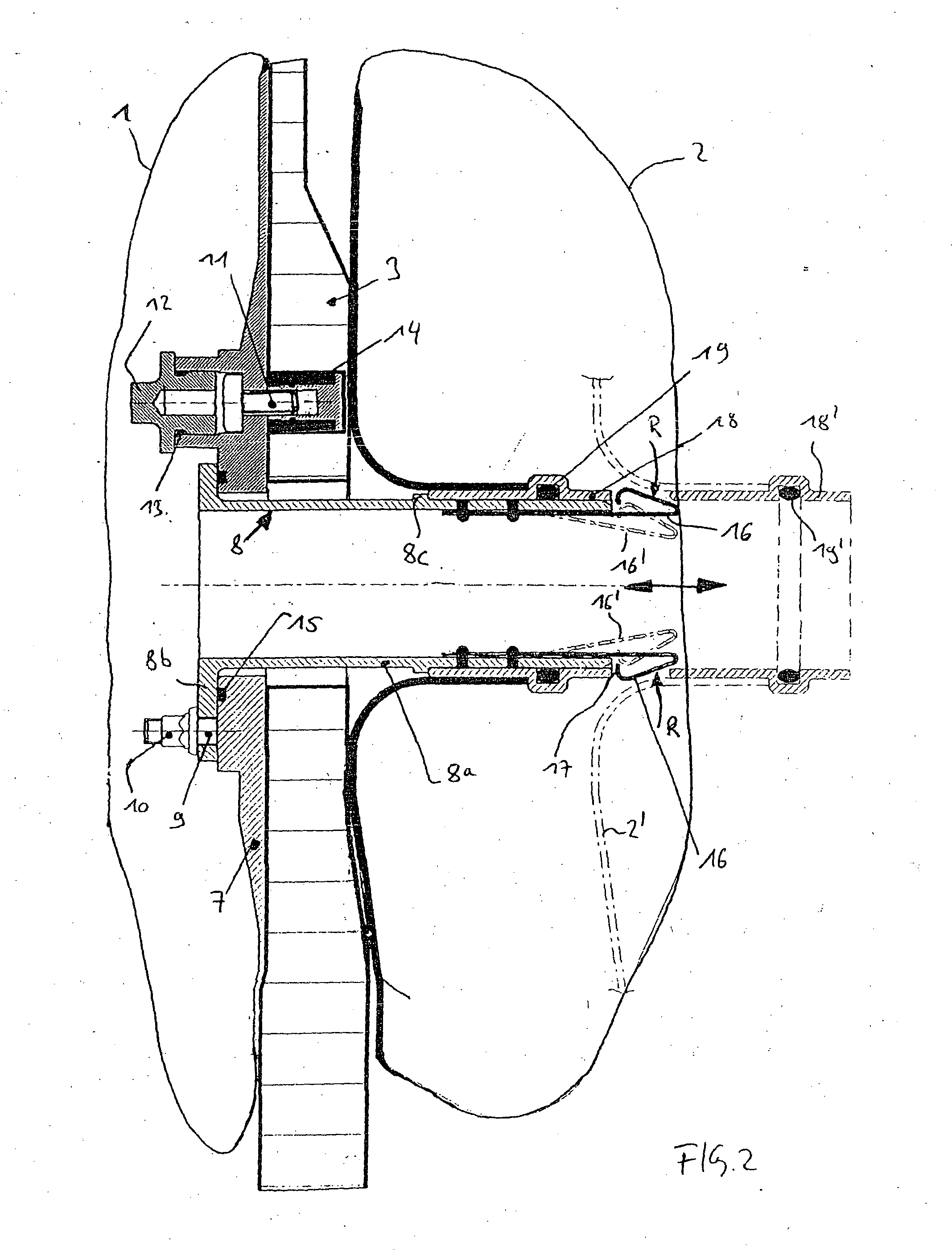
[0020] The connection arrangement according the invention shown in detail in FIG. 2 comprises a first connecting element 8, a second connecting element 18 as well as a latching device configured as a spring 16.

[0021] As shown in FIG. 2, the first connecting element 8 consists of a cylindrical or tubular area 8a, a flange 8b and a stop 8c that is formed on the outside of the tubular area 8a. Here, the first connecting element 8 is attached to a fitting 7 of the first tank 1 by means of several bolts 9 and nuts 10. A flexible tank pouch of the first tank 1 is attached to the fitt...


PUM

PropertyMeasurementUnit
angleaaaaaaaaaa
flexibleaaaaaaaaaa
stabilityaaaaaaaaaa

Abstract

A connection arrangement for detachably connecting a first flexible tank and a second flexible tank in an aircraft includes a latching device, a first tubular connecting element attached to the first tank, and a second tubular connecting element attached to the second tank. The first and the second connecting elements are detachably connected to each other using the latching device. In a connected state of the connecting elements, fluid exchange can take place between the first and the second tanks via the first and the second connecting elements, the latching device is disposed inside one of the first and second flexible tanks and is actuatable from outside the respective flexible tank.

Description

[0001] Priority is claimed to German patent application no. DE 102 29 803.3, filed on Jul. 3, 2002, the subject matter of which is incorporated by reference herein. BACKGROUND [0002] The present invention relates to a connection arrangement to detachably connect two flexible tanks in aircraft. [0003] It is a known practice to employ flexible tanks of an aircraft such as, for instance, helicopters. In particular, due to design-related space constraints, several small tanks that are connected to each other are often used instead of one large tank. Due to the tight space available, it is frequently difficult to install such a plurality of tanks. Moreover, it would be desirable, for example, in order to perform repair work, to be able to simply remove one or all of the tanks so as to better gain access to the repair sites in question or to have more space available for carrying out the repair. SUMMARY OF THE INVENTION [0004] An objective of the present invention is to provide a connecti...

Claims


Application Information

Patent Timeline
Patent Type & Authority Applications(United States)
IPC IPC(8): B64D37/06
CPCY10S220/905B64D37/06
Inventor RODOUSAKIS, ELEFTHERIOSKIOWSKY, HARALD
Owner AIRBUS HELICOPTERS DEUT GMBH
Why Eureka
Try Eureka