Heating/cooling method, manufacturing method of image displaying apparatus, heating/cooling apparatus, and heating/cooling processing apparatus

a manufacturing method and image displaying technology, applied in the manufacture of electrode systems, electric discharge tubes/lamps, baking ovens, etc., can solve the problems of deteriorating heating efficiency upon heating and low cooling speed of substrates, and achieve the effect of high speed

Inactive Publication Date: 2005-02-17
CANON KK
View PDF6 Cites 18 Cited by
  • Summary
  • Abstract
  • Description
  • Claims
  • Application Information

AI Technical Summary

Benefits of technology

[0011] It is an object of the invention to provide a heating / cooling method, a manufacturing method of an image displaying apparatus, a heating / cooling apparatus, and a heating / cooling processing apparatus, in which heating and cooling of a substrate can be executed at a high speed.

Problems solved by technology

However, according to the substrate heating apparatus disclosed in Japanese Patent Application Laid-Open No. 2003-59788, there occurs such a problem that when the substrate is cooled, the heat generated from the substrate is reflected by the heat reflecting plate and the reflected heat is again directed toward the substrate, so that a cooling speed of the substrate becomes low.
H07-216550, there is such a problem that heating efficiency upon heating deteriorates considerably.

Method used


Image

  • Heating/cooling method, manufacturing method of image displaying apparatus, heating/cooling apparatus, and heating/cooling processing apparatus
  • Heating/cooling method, manufacturing method of image displaying apparatus, heating/cooling apparatus, and heating/cooling processing apparatus
  • Heating/cooling method, manufacturing method of image displaying apparatus, heating/cooling apparatus, and heating/cooling processing apparatus

Examples


embodiment 1

[0040] (Embodiment 1)

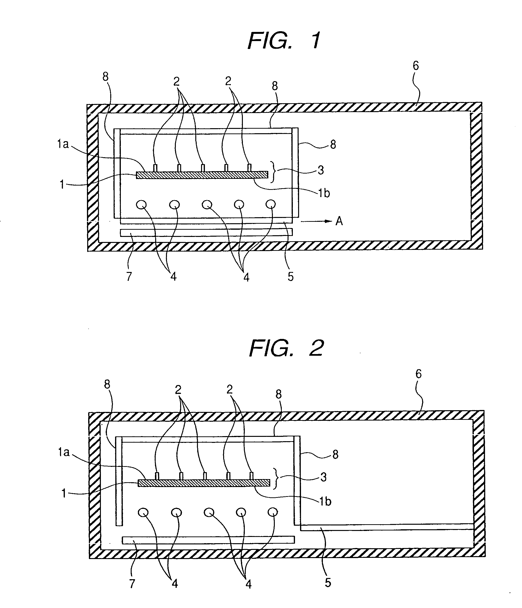
[0041]FIG. 1 is a cross sectional view schematically showing a heating / cooling apparatus of the first embodiment of the invention. In more detail, FIG. 1 is the cross sectional view schematically showing the heating / cooling apparatus when a heating process is executed.

[0042] In FIG. 1, the heating / cooling apparatus includes heaters 4, a heat reflecting member 5, a chamber 6, a cooling plate 7, and heat reflecting members 8.

[0043] A plurality of supporting pins (not shown) for supporting a substrate 3 (work) in which members 2 are provided only on one surface 1a of a base material 1 are provided in the chamber 6.

[0044] The substrate 3 to which the heating process is executed is put on the supporting pins so that the other surface 1b of the base material 1 is come into contact with the supporting pins in the chamber 6.

[0045] The heaters 4 are arranged in positions where they face the other surface 1b of the substrate 3 when the substrate 3 is put on the suppor...

embodiment 2

[0078] (Embodiment 2)

[0079] The second embodiment of the invention will now be described. The embodiment relates to an example showing another method of setting the area of the surface (heat reflecting surface) of the heat reflecting member which faces the substrate 3 to be narrower than that of the surface (heat reflecting surface) of the heat reflecting member upon heating in the cooling step.

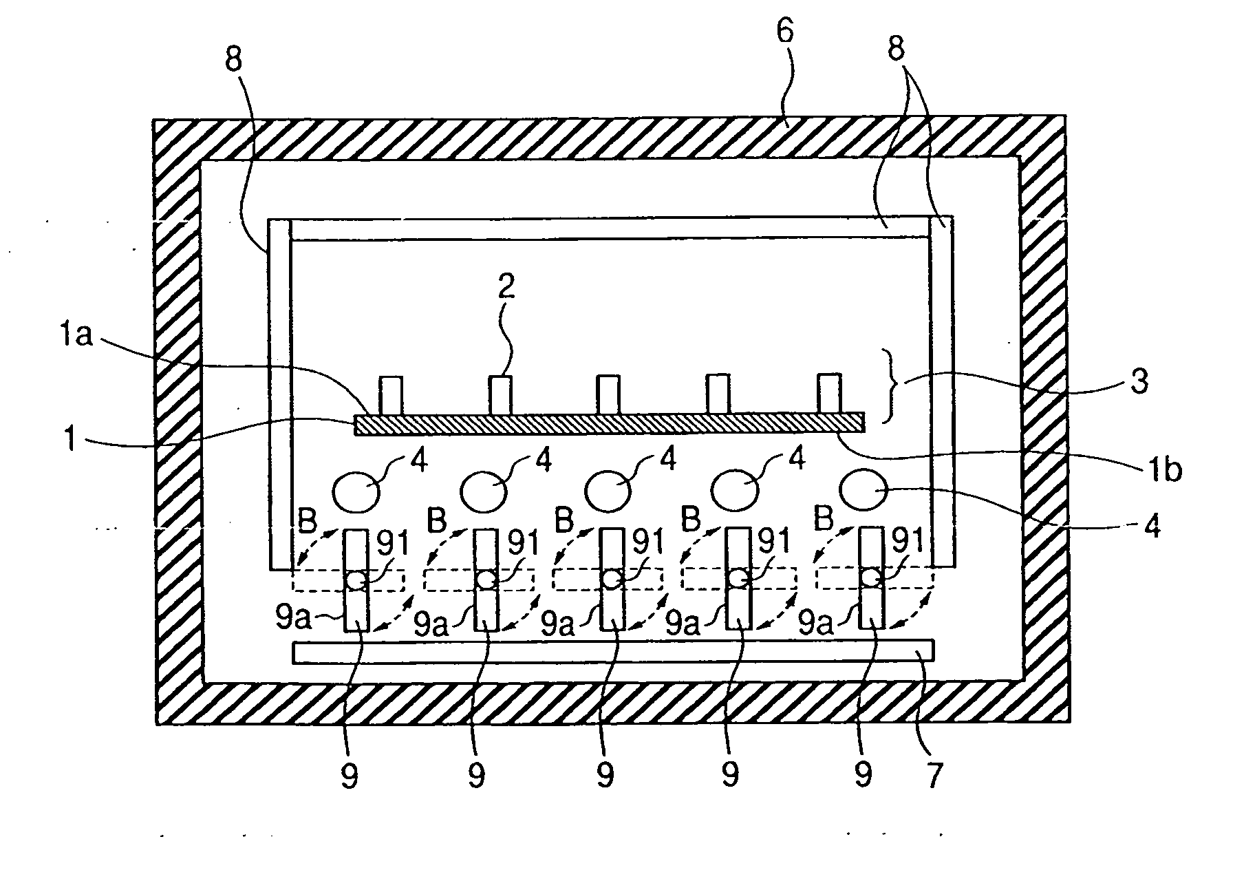
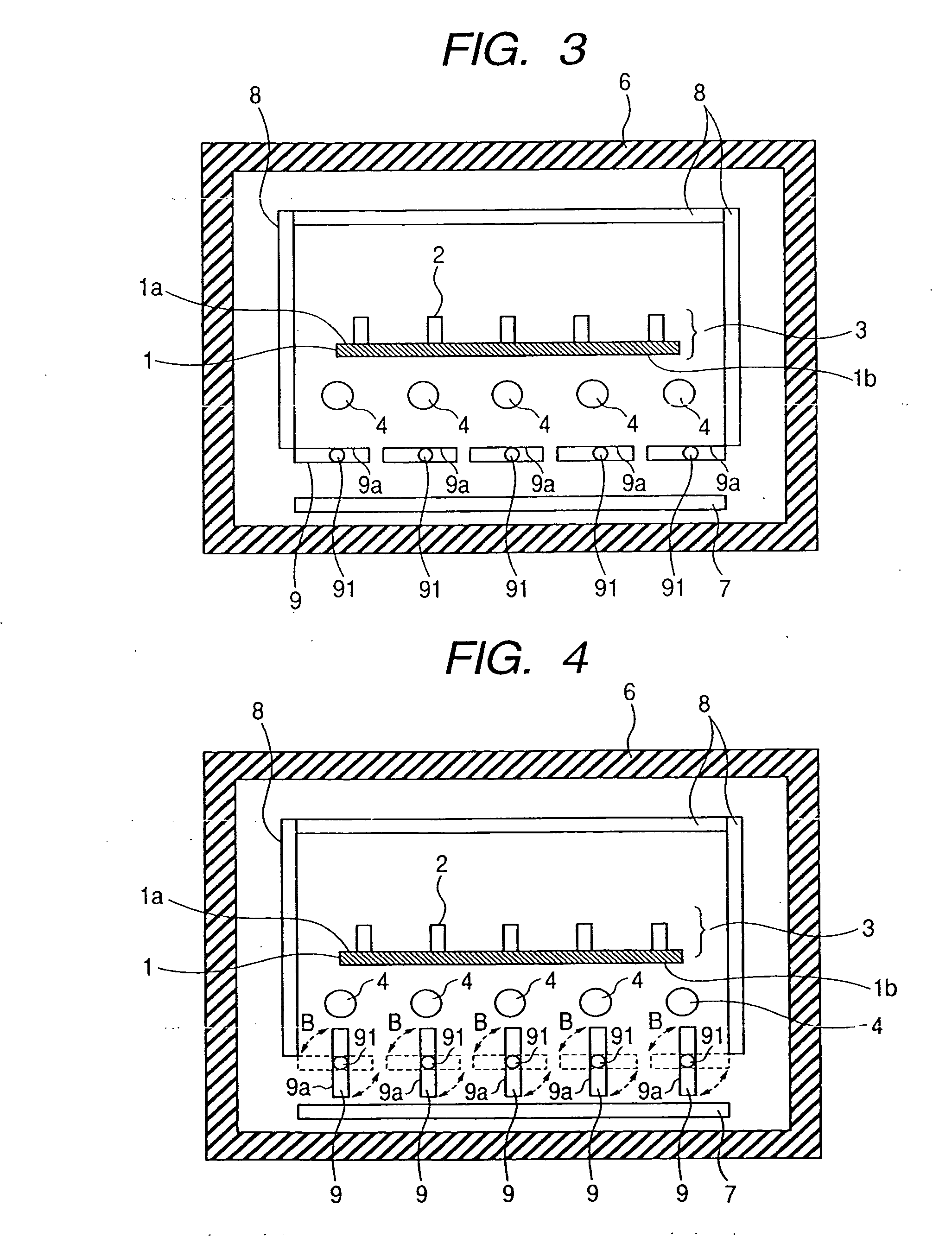
[0080]FIGS. 3 and 4 are cross sectional views schematically showing a heating / cooling apparatus of the second embodiment of the invention. In more detail, FIG. 3 is a cross sectional view schematically showing the heating / cooling apparatus at the time of executing the heating process. FIG. 4 is a cross sectional view schematically showing the heating / cooling apparatus at the time of executing the cooling process. In FIGS. 3 and 4, component elements having the same constructions as those shown in FIG. 1 are designated by the same reference numerals.

[0081] In FIGS. 3 and 4, the heating / cooli...

embodiment 3

[0091] (Embodiment 3)

[0092] The third embodiment of the invention will now be described. The embodiment relates to an example showing another method of setting the area of the surface of the heat reflecting member which faces the substrate 3 to be narrower than that of the surface of the heat reflecting member upon heating in the cooling step.

[0093]FIGS. 5 and 6 are cross sectional views schematically showing a heating / cooling apparatus of the third embodiment of the invention. In more detail, FIG. 5 is a cross sectional view schematically showing the heating / cooling apparatus at the time of executing the heating process. FIG. 6 is a cross sectional view schematically showing the heating / cooling apparatus at the time of executing the cooling process. In FIGS. 5 and 6, component elements having the same constructions as those shown in FIG. 1 are designated by the same reference numerals.

[0094] In FIGS. 5 and 6, the heating / cooling apparatus includes the heaters 4, chamber 6, coolin...


PUM

PropertyMeasurementUnit
thicknessaaaaaaaaaa
thicknessaaaaaaaaaa
sizeaaaaaaaaaa

Abstract

A heating/cooling method, a manufacturing method of an image displaying apparatus, a heating/cooling apparatus, and a heating/cooling processing apparatus, in which the heating and cooling of a substrate can be executed at a high speed are provided.

Description

[0001] This application claims priority from Japanese Patent Applications No. 2003-272431 filed on Jul. 9, 2003 and No. 2003-328290 filed on Sep. 19, 2003, which are hereby incorporated by reference. BACKGROUND OF THE INVENTION [0002] 1. Field of the Invention [0003] The invention relates to a heating / cooling method, a manufacturing method of an image displaying apparatus, a heating / cooling apparatus, and a heating / cooling processing apparatus. [0004] 2. Related Background Art [0005] Hitherto, when a substrate constructing a predetermined apparatus is manufactured, there is a case of executing a heating process for heating the substrate. [0006] A substrate heating apparatus for executing the heating process has been disclosed in Japanese Patent Application Laid-Open No. 2003-59788. [0007] The substrate heating apparatus disclosed in Japanese Patent Application Laid-Open No. 2003-59788 comprises: a heating plate for heating the substrate; a heat reflecting plate arranged so as to fac...

Claims


Application Information

Patent Timeline
Patent Type & Authority Applications(United States)
IPC IPC(8): C03B29/02C03B32/00C03C23/00F27B17/00F27D19/00F27D99/00H01J9/24
CPCC03B29/025C03B32/00C03C23/007F27B17/0016H01J2211/36F27D99/0001H01J9/241H01J9/242F27D19/00
Inventor YOSHIMURA, MASANAOYAKOU, TAKESHIKOMURA, AKIHIKOKIMURA, AKIHIROKAMATA, SHIGETO
Owner CANON KK
Why Eureka
Try Eureka