Power supplying apparatus and method for a vehicle

a technology for power supply apparatus and vehicle, which is applied in the direction of emergency power supply arrangements, electric devices, transportation and packaging, etc., can solve the problems of provisionally stopping or reducing the power supplied to the load, the inability to supply power to the load on the other system free, and the inability to meet the requirements of power supply systems

Inactive Publication Date: 2005-02-17
HITACHI LTD
View PDF5 Cites 66 Cited by
  • Summary
  • Abstract
  • Description
  • Claims
  • Application Information

AI Technical Summary

Benefits of technology

[0004] In the conventional technique disclosed in JP-A2000-312444, however, the power supplies and the load are electrically disconnected from each other while the circuit is switched, and therefore the problem is posed that the power supplied to the load is provisionally stopped or reduced.

Problems solved by technology

In the conventional technique disclosed in JP-A2000-312444, however, the power supplies and the load are electrically disconnected from each other while the circuit is switched, and therefore the problem is posed that the power supplied to the load is provisionally stopped or reduced.
According to the prior art disclosed in JP-A-11-122701, on the other hand, in the case where the loads in one system are shorted or a part of the power supplying lines in one system develop a ground fault, the output voltages of both systems drop, thereby often making it impossible to supply power to the loads on the other system free of the fault.
With regard to the brake or the power steering system which is totally prohibited from losing the function to assure vehicle safety, the conventional double power supply systems are not a satisfactory solution, and a fail-safe mechanism constituted of a hydraulic or mechanical system is required in case of power failure.
This leads to the problem of a lower fuel consumption efficiency due to the increased cost and weight of the vehicle.

Method used


Image

  • Power supplying apparatus and method for a vehicle
  • Power supplying apparatus and method for a vehicle
  • Power supplying apparatus and method for a vehicle

Examples


first embodiment

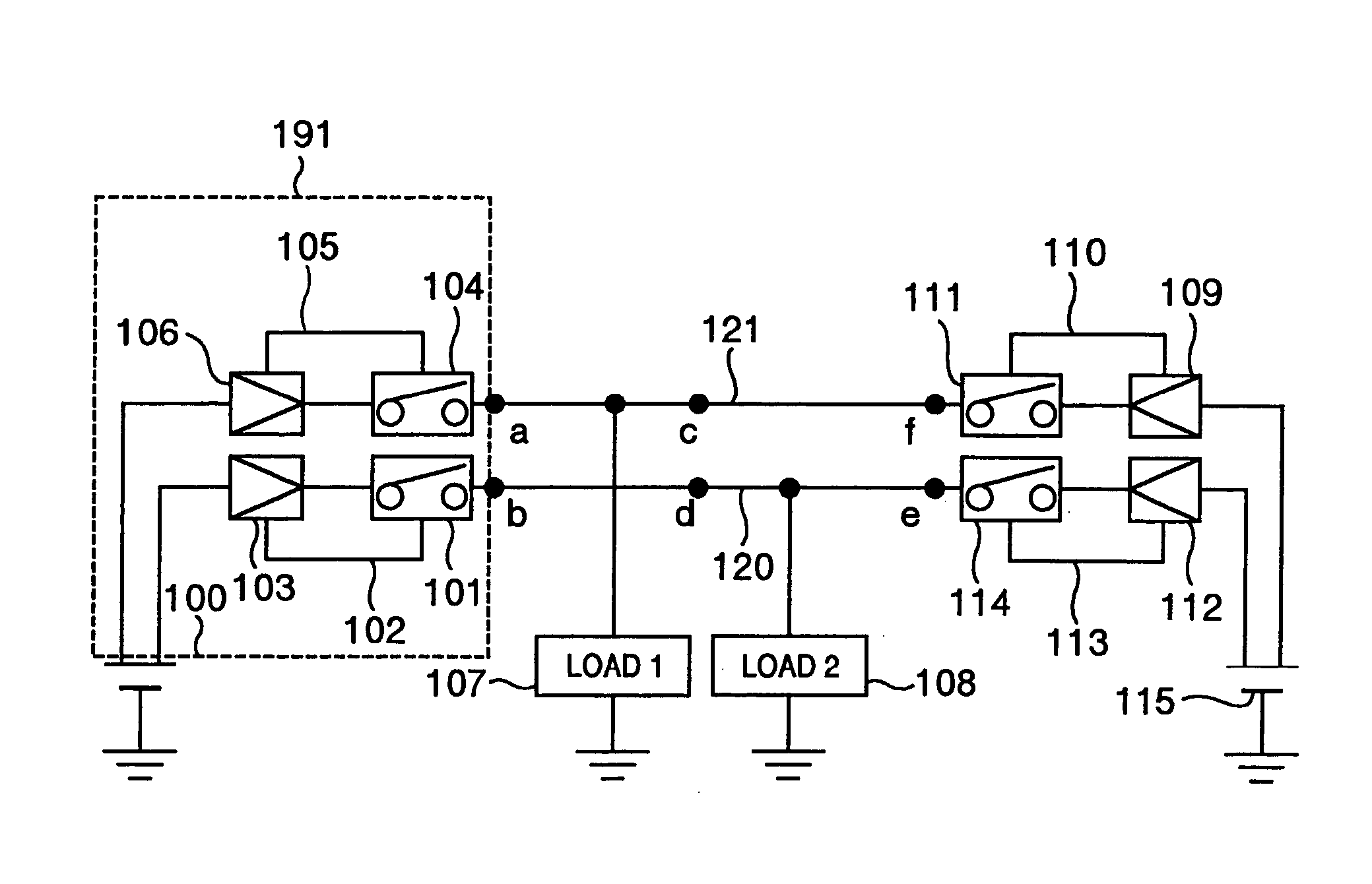
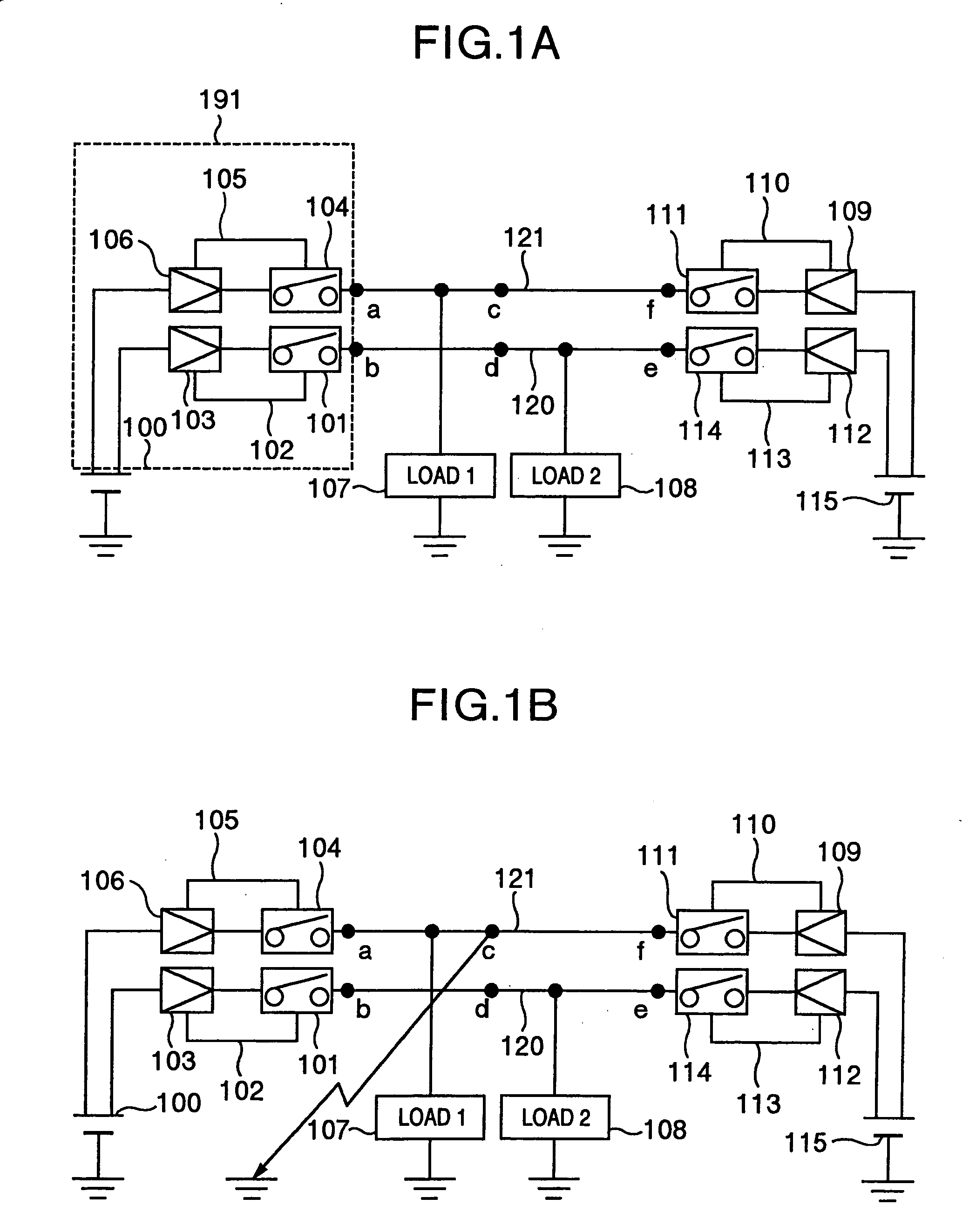
[0025]FIG. 1 shows this invention. In FIG. 1A, reference numerals 100, 115 designate DC power supplies, numerals 101, 104, 111, 114 circuit breaker units, numerals 103, 106, 109, 112 fault detection units, numerals 102, 105, 110, 113 signal lines, numerals 107, 108 loads, and numerals 120, 121 power supplying lines. Power is adapted to be supplied to a load 1 (107) and a load 2 (108) from both the power supplies 100 and 115 through a circuit breaker unit and a fault detection unit. Specifically, power can be supplied to the load 1 (107) from the power supply 100 through the fault detection unit 106 and the circuit breaker unit 104 on the one hand and from the power supply 115 through the fault detection unit 109 and the circuit breaker unit 111 on the other hand. The load 2 (108) is similarly adapted to be supplied with power from the power supply 100 through the fault detection unit 103 and the circuit breaker unit 101 on the one hand and from the power supply 115 through the fault...

fourth embodiment

[0064] the invention is shown in FIG. 9.

[0065] The embodiment shown in FIG. 9 represents an electrical brake system. The electrical brake has various advantages including the elimination of the brake oil piping and the braking performance secured independent of the brake oil temperature characteristic, and is a promising technique as a future vehicle brake. In view of the fact that the braking force is generated by activating an electrical actuator, however, the braking function is lost when power supply is stopped. The electrical brake system, therefore, requires a configuration in which power continues to be supplied to the electrical actuators at the time of such an accident as a collision as well as under normal running conditions.

[0066] In FIG. 9, numerals 40, 44, 59, 60 designate actuators for the electrical brakes arranged on the wheels of the vehicle, numeral 46 a sensor simulator for converting the amount of brake operation (the brake pedal angle, brake pedal depression pr...

third embodiment

[0074] Next, the connection between the main C / U 64 and the power supplies is explained. In FIG. 9, the main C / U 64 is supplied with power from the main battery 49 through the fuse 52 and the diode 61 on the one hand, and from the subsidiary battery 56 through the fuse 53 and the diode 61 shared by the main battery 49. Further, power is supplied from the main battery 49 through the fuse 54 and the diode 62, and also from the subsidiary battery 56 through the fuse 55 and the diode 62 shared by the main battery 49. This configuration is considered as an application of the invention.

[0075] With this configuration, the power feed to the main C / U 64 can be secured against the faults such as the ground fault or the disconnection of the power supplying line 42 or 43, the fall of the main battery 49 or the subsidiary battery 56 or the shorting of the actuator 40, 44, 59, 60.

[0076] The aforementioned configuration also makes it possible to secure the operation of the actuators for at least ...


PUM


Abstract

A power supplying apparatus and method for a vehicle are disclosed. A plurality of loads and a plurality of power supplies are connected to each other in such a manner that one of the loads is connected to a plurality of the power supplies, and one of the plurality of the power supplies is connected to a plurality of the loads. Further, the power supplies and the loads are connected through a breaker unit for electrically disconnecting the circuit under predetermined conditions and a unidirectional conductive unit for allowing the current to flow in one direction and blocking the current in the opposite direction.

Description

BACKGROUND OF THE INVENTION [0001] The present invention relates to a power supplying apparatus and method for a vehicle, in which power is supplied from power supplies to electrical loads mounted on the vehicle. [0002] In recent years, such devices as the brake, the gear shift mechanism of the transmission of an automotive vehicle which have conventionally been driven by a hydraulic or mechanical system have come to be driven electrically. The high controllability of the electrical equipment improves the safety and dynamism of the vehicle. The electrical equipment, however, requires electric power as a drive source, and once power supply is stopped, loses the function thereof. Therefore, a high reliability is required of the power supply system. For this reason, double power supply systems have been conceived in which power can be supplied from the desired one of the power supplies by switching a circuit (JP-A-2000-312444). [0003] On the other hand, a system has been developed in w...

Claims


Application Information

Patent Timeline
Patent Type & Authority Applications(United States)
IPC IPC(8): B60R16/02B60R16/03B60T17/18B62D5/04H02H3/087H02J1/08H02J1/10H02J7/00H02J7/14H02J9/06
CPCB60R16/03H02H3/087H02J7/1423H02J1/108H02J1/08H02J9/06H02J2310/46
Inventor KURAMOCHI, YUICHIMANAKA, TOSHIOMATSUBARA, KENICHIRO
Owner HITACHI LTD
Why Eureka
Try Eureka