[0020] Signals reflected from a radome surface that is tangential to the desired
signal direction would be straight back into the signal path, contributing to the
return loss of the reflector antenna. Also, reflections
proximate the feed
assembly encounter multiple surfaces from which to launch reflections that may finally be directed back to the feed, further contributing to return loss. A radome with a small
radius reflects signals out of the signal path but also degrades the
far field radiation pattern. Further, radomes with small radius configurations have an extended dimension along the signal axis of the reflector antenna, increasing the wind load and associated
mechanical strength requirements for the reflector antenna and antenna support structure. The present invention utilizes a very large radius in an outer portion and a smaller radius for a central portion that is significantly larger (has a focal point at the reflector vertex area rather than the back side of the
antenna feed) than central areas of two section radomes in the prior art. The radome configuration according to the invention provides return loss, signal pattern improvements and a reduction in wind load.
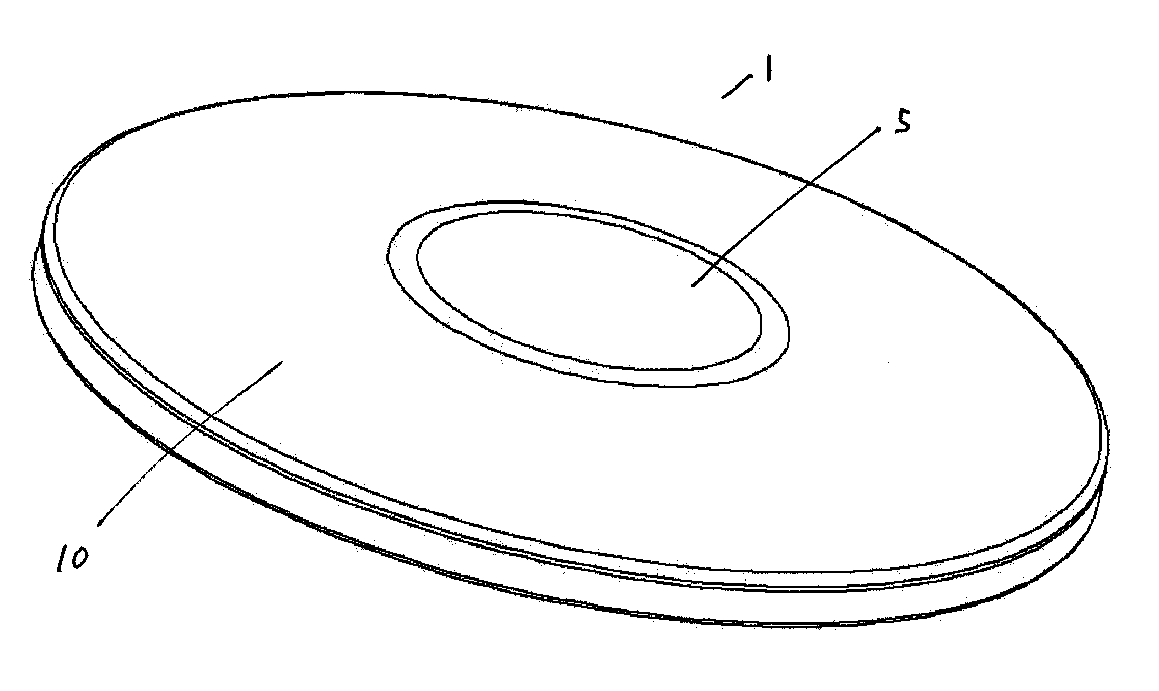
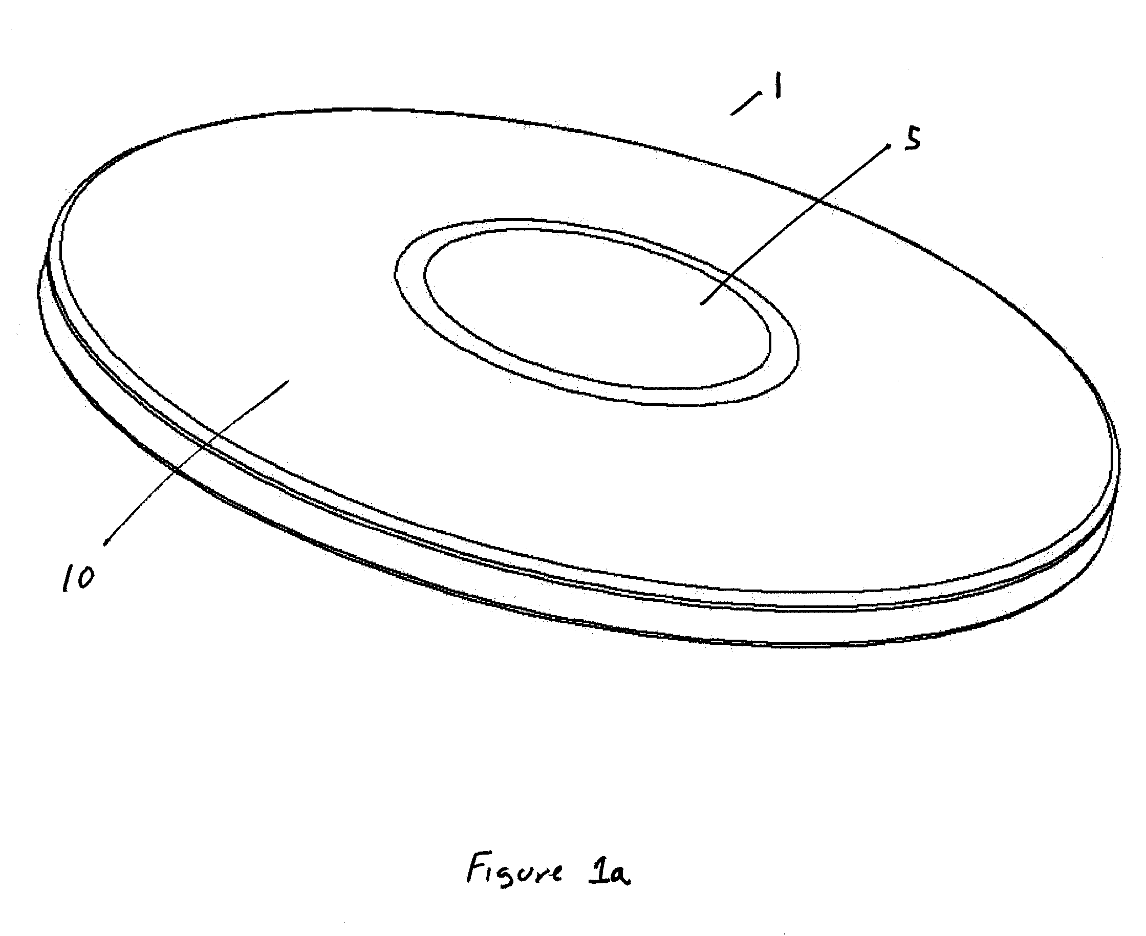
[0022] As shown by FIG. 3, the different radii of the central and outer portions 5, 10 creates a reflection pattern that varies depending upon the radome 1 surface that incident RF 12 reflects from. The selected central portion 5 radius will depend upon the particular
focal length and
diameter of the desired reflector. The central portion 5 radius is configured so that an inner reflected component 13 of RF signals incident upon the central portion 5 is focused upon the reflector 14 vertex area 16. The vertex area 16, shaded by the
antenna feed assembly 17, is not a reflector 14 surface used to project the RF signal into the desired
radiation pattern. RF absorbing material 18 placed at the vertex area 16 may be used to absorb the portion of the reflected component 13 that is reflected by the radome 1 central portion 5 thereby preventing further reflections from the vertex area 16 that may be aligned with the antenna feed which would otherwise contribute to the return loss of the reflector antenna, overall.
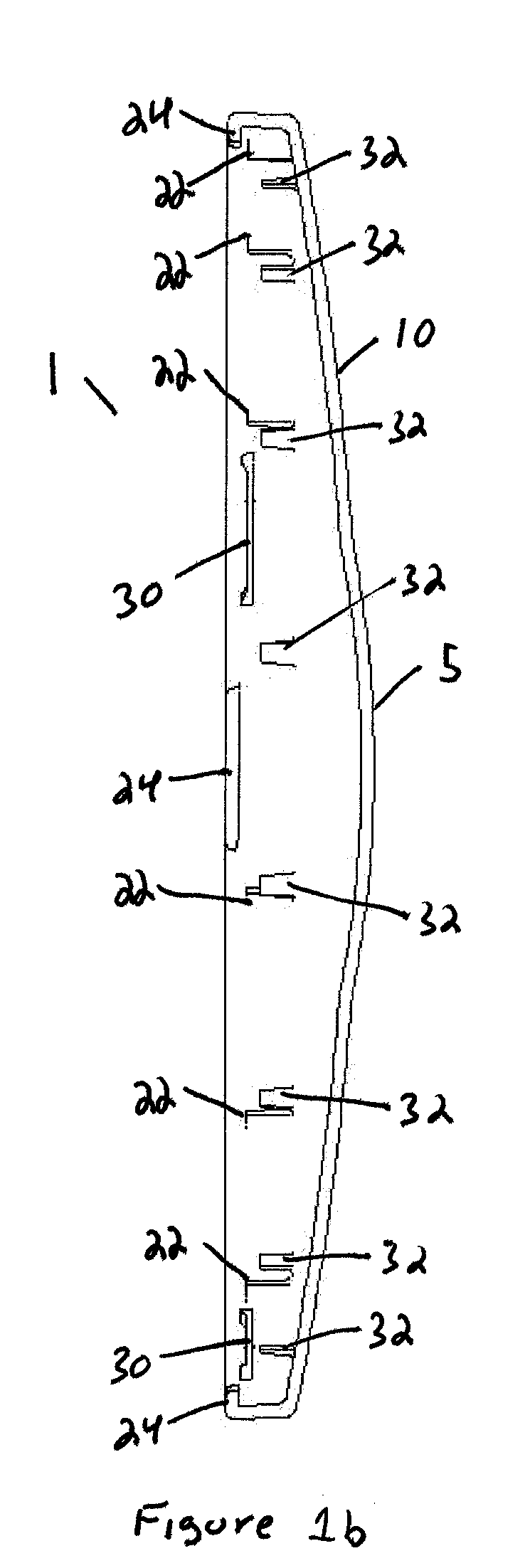
[0027] The radome 1 is secured by the interference between the tabs 24 and the periphery of the reflector 14 without
cut outs 26 and the locking clips 30 within the
cut outs 26, but otherwise floats in place. Therefore, there is no need for a mechanical
fastener such as a rigid screw connection between the two components. Because both the radome 1 and the reflector 14 are free to expand or contract separately, according to the expansion coefficient of each, the chance of unequal expansion between the two causing a deformation of the radome 1 and or reflector 14 is reduced.
[0028] The signal pattern of the reflector antenna may be improved by adding a shroud lined with RF absorbing material around the periphery of the reflector. However, prior shrouds created a significant increase in the wind load of the resulting reflector antenna. Deep dish reflector configurations decrease the need for a full shroud. To obtain the partial benefit of a full shroud with a deep dish reflector 14, without increasing the windload of the antenna, RF absorbing material 18 may be added at the periphery of the reflector, under the radome 1. Absorber retainers 32 may be formed in the periphery of the radome 1 as mounting structure for retaining strip(s) or a ring of RF absorbing material 18.
[0029] The present invention brings to the art a radome with an improved RF signal pattern, return loss, wind loading and
snow / ice buildup characteristics. Further the radome has a secure radome to reflector antenna mounting that allows relative expansion of the different components and does not require tools or multiple extra components that may create a drop
hazard, be easily misplaced and or lost.

