Method for fabricating transflective color LCD device and the transflective color LCD device

Inactive Publication Date: 2005-02-17
LG DISPLAY CO LTD
View PDF9 Cites 24 Cited by
  • Summary
  • Abstract
  • Description
  • Claims
  • Application Information

AI Technical Summary

Benefits of technology

[0042] An object of the present invention is to provide a simple method fo

Problems solved by technology

Therefore, high power consumption due to the back light is a greater disadvantage of the transmission type LCD device.
However, the reflection type LCD device is useless when

Method used


Image

  • Method for fabricating transflective color LCD device and the transflective color LCD device
  • Method for fabricating transflective color LCD device and the transflective color LCD device
  • Method for fabricating transflective color LCD device and the transflective color LCD device

Examples


Example

[0072] Reference will now be made in detail to the preferred embodiments of the present invention, which are illustrated in the accompanying drawings.

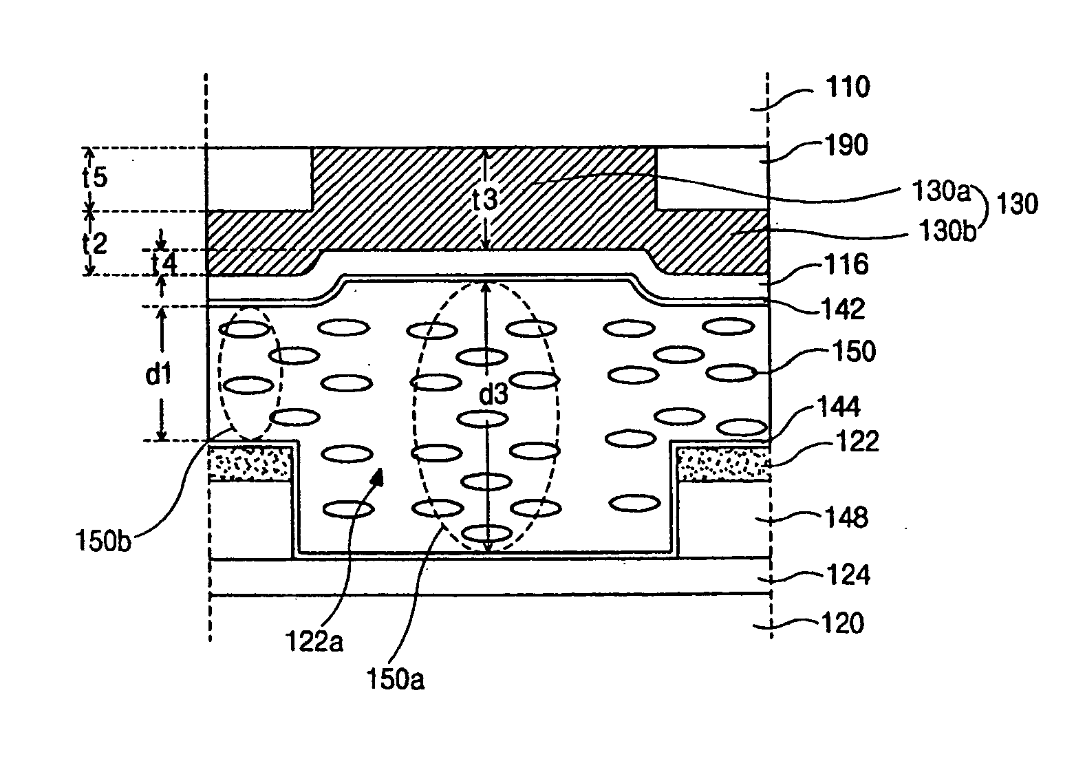
[0073]FIG. 8 is a cross-sectional view illustrating an LCD device according to the preferred embodiment of the present invention. As shown, between the upper and lower substrates 110 and 120, a liquid crystal layer 150 is interposed. The upper substrate 110 has the color filter layer 130 and common electrode 116, which are sequentially formed on the surface opposing the lower substrate 120. On a surface of the common electrode 116, an upper alignment layer 142 is formed to face the liquid crystal layer 150. Between the upper substrate 110 and the color filter layer 130, a buffer layer 190 is interposed. In addition, on the exterior surface of the upper substrate 110, a retardation film 146 and an upper polarizer 154 are sequentially disposed. Though a half wave plate (HWP) is used as the retardation layer 146 for the preferred embodim...


PUM


Abstract

A color filter substrate includes a substrate, a plurality of buffer layers respectively on the substrate, the plurality of buffer layers being spaced apart from adjacent buffer layers with an interval such that they have the shape of a matrix, a plurality of color filter layers on the buffer layers such that the plurality of color filter layers have the shape of matrix, each color filter layer having first and second portions, the first portion disposed in the gap between two adjacent buffer layers while the second portion is disposed on upper surfaces of the two adjacent buffer layers, the plurality of color filter layers being used for the transflective LCD device; and a common electrode on the plurality of color filter layers. In fabricating the color filter layer, the first and second portions of the color filter layer are integrally formed. Therefore, a simple fabricating process is achieved.

Description

[0001] This patent application claims the benefit of Korean patent application No. 2000-9979, filed on Feb. 29, 2000, the entirety of which is hereby incorporated by reference for all purposes as if fully set forth herein. BACKGROUND OF THE INVENTION [0002] 1. Field of the Invention [0003] The present invention relates to a liquid crystal display device, and more particularly to a transflective liquid crystal display (LCD) device implementing a color filter having various thickness. [0004] 2. Discussion of the Related Art [0005] LCD devices are usually classified into transmission type and reflection type according to their difference in a light source. [0006] The transmission type LCD device uses light incident from a back light that is attached to a rear surface of a liquid crystal panel. The light is incident to a liquid crystal layer of the liquid crystal panel, and is absorbed or passes through the liquid crystal layer according to proper alignments of the liquid crystal layer....

Claims


Application Information

Patent Timeline
IPC IPC(8): G02F1/1333G02F1/1335
CPCG02F1/133371G02F1/133555G02F1/133514
Inventor KIM, YONG-BEOMLEE, JEONG-HWAN
Owner LG DISPLAY CO LTD
Why Eureka
Try Eureka