Mitigation of plasma-inductor termination

a plasma-inductor and termination technology, applied in the field of ion and plasma sources, can solve the problems of overheating of the inductor, excessive rf power to generate a useful extracted ion current, and complicated beam characterization, etc., and achieve the effect of reducing the variations of ion current density

Active Publication Date: 2011-07-07
KAUFMAN & ROBINSON
View PDF13 Cites 6 Cited by
  • Summary
  • Abstract
  • Description
  • Claims
  • Application Information

AI Technical Summary

Benefits of technology

[0021]A still further specific object of the invention is to mitigate the variations of ion current density in the beam from an inductively coupled radio-frequency ion

Problems solved by technology

This location can result in overheating of the inductor, but it is effective in coupling the rf energy to the discharge region.
This departure from symmetry causes a variety of problems.
Even the characterizatio

Method used


Image

  • Mitigation of plasma-inductor termination
  • Mitigation of plasma-inductor termination
  • Mitigation of plasma-inductor termination

Examples


Embodiment Construction

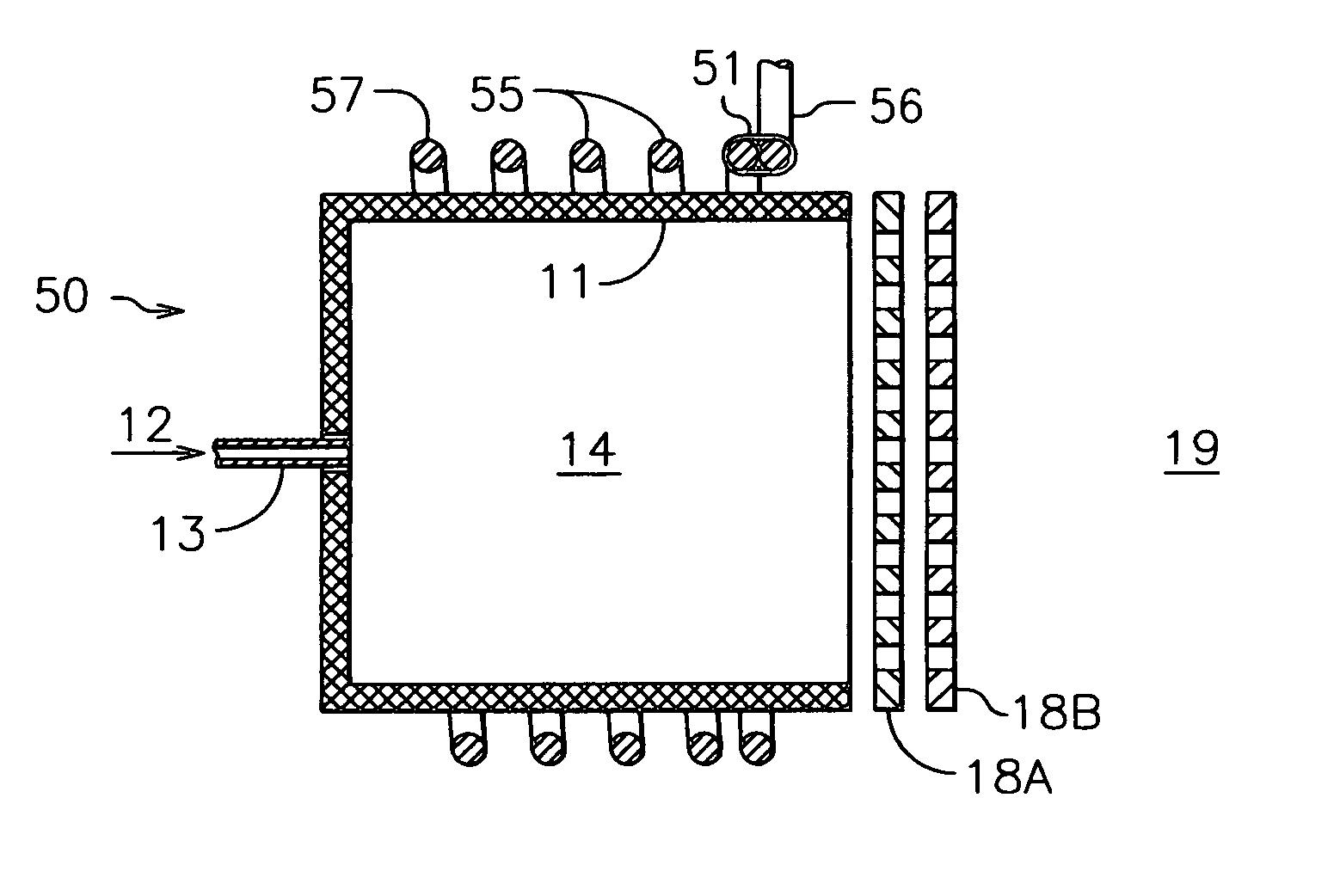
[0053]Referring to FIG. 6, there is shown an embodiment of the present invention. Ion source 50 is similar to ion source 10 in FIG. 1 in configuration, except that inductor 15 with ends 16 and 17 is replaced with inductor 55 which has ends 56 and 57, but with the termination at end 56 comprised of one turn, shorted to itself by connector 51. The shorted turn can be considered as a turn at one end of inductor 55, shorted to itself or, alternatively, a shorted turn in electrical contact at one or more locations with the turn at one end of inductor 55. The operation of source 50 is also generally similar to that of source 10. However, a significant difference in operation is found in the profile of ion current density.

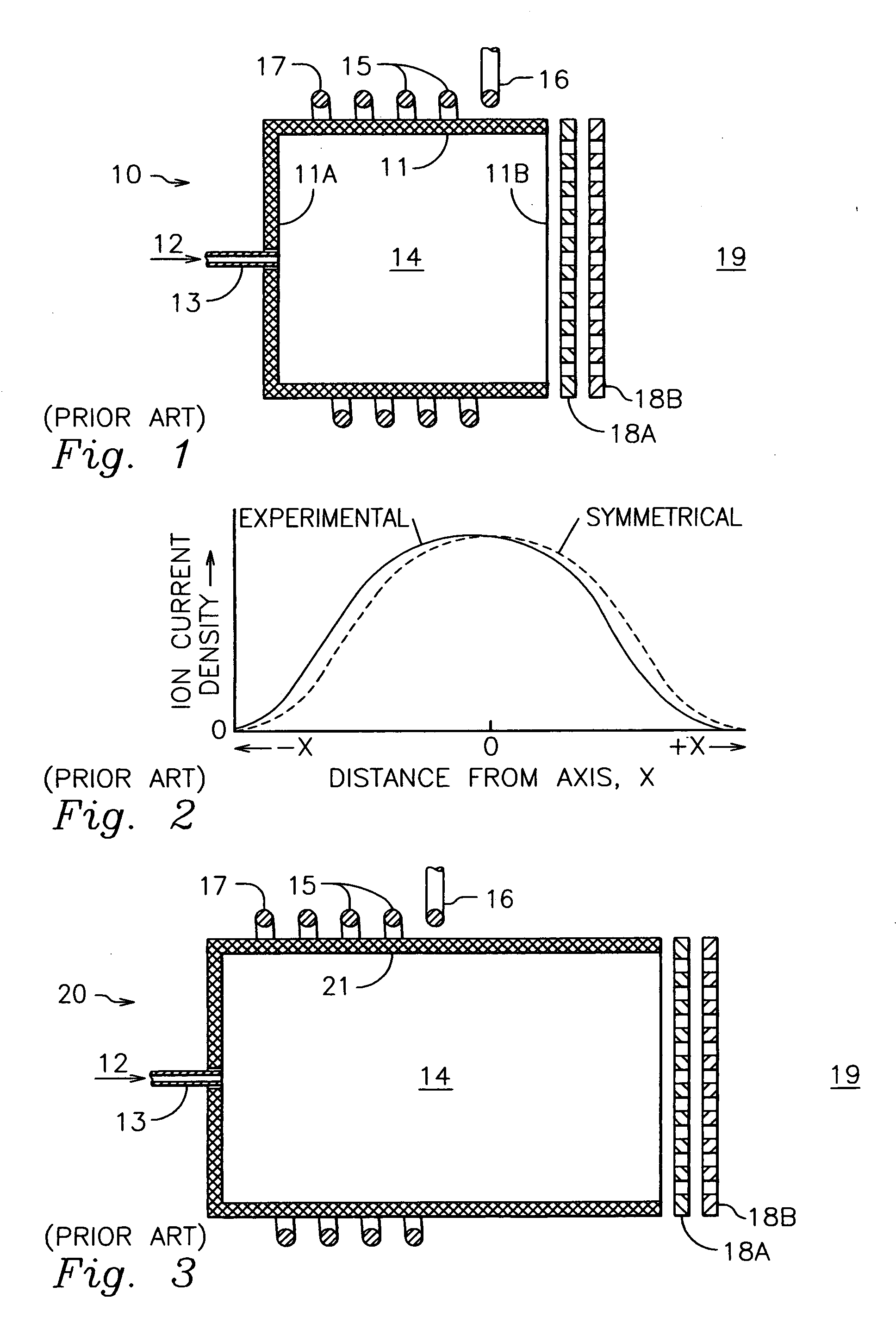
[0054]Referring to FIG. 7, there are shown the profiles of an inductively coupled rf ion source both with (FIG. 6) and without (FIG. 1) a shorted turn at the end of the inductor. The gridded ion source used had a beam diameter of 14 cm. The apertures in the grids were 2 m...


PUM


Abstract

In accordance with one embodiment of the present invention, the dielectric discharge chamber of a generally axially symmetric ion source has a hollow cylindrical shape. One end of the discharge chamber is closed with a dielectric wall. The working gas is introduced through an aperture in the center of this wall. The ion-optics grids are at the other end of the discharge chamber, which is left open. The inductor is a helical coil of copper conductor that surrounds the cylindrical portion of the dielectric discharge chamber. The modification that produces uniformity about the axis of symmetry is a shorted turn of the helical-coil inductor at the end of the inductor closest to the ion-optics grids.

Description

CROSS-REFERENCE TO RELATED APPLICATION[0001]This application is based upon, and claims priority from, our Provisional Application No. 61 / 335,302, filed Jan. 5, 2010.FIELD OF INVENTION[0002]This invention relates generally to ion and plasma sources, and more particularly it pertains to those sources in which ions are generated with an inductively coupled radio-frequency discharge.BACKGROUND ART[0003]A plasma can be defined as an electrically conducting gas that satisfies quasi-neutrality. For singly charged ions, the type most often generated in ion and plasma sources, this means that the density of electrons and ions is approximately equal (ne≈ni). An ion or plasma source typically has a discharge region in which ions are generated by the collisions of energetic electrons with molecules of the working gas, a region of ion acceleration, and a region through which the beam of energetic ions travels after it leaves the source. Beams from industrial ion or plasma sources are used for et...

Claims


Application Information

Patent Timeline
IPC IPC(8): H05B31/26
CPCH01J27/16H05H2001/4667H05H1/46H05H1/4652
Inventor KAUFMAN, HAROLD R.KAHN, JAMES R.
Owner KAUFMAN & ROBINSON
Why Eureka
Try Eureka