Liquid Tank With An Ultrasonic Sensor

Active Publication Date: 2016-07-28
VITESCO TECH GMBH
View PDF0 Cites 4 Cited by
  • Summary
  • Abstract
  • Description
  • Claims
  • Application Information

AI Technical Summary

Benefits of technology

[0012]The present disclosure provides a liquid tank with an ultrasonic sensor distinguished b

Problems solved by technology

In addition, the round surface of the cylinders impedes the

Method used


Image

  • Liquid Tank With An Ultrasonic Sensor
  • Liquid Tank With An Ultrasonic Sensor

Examples


Embodiment Construction

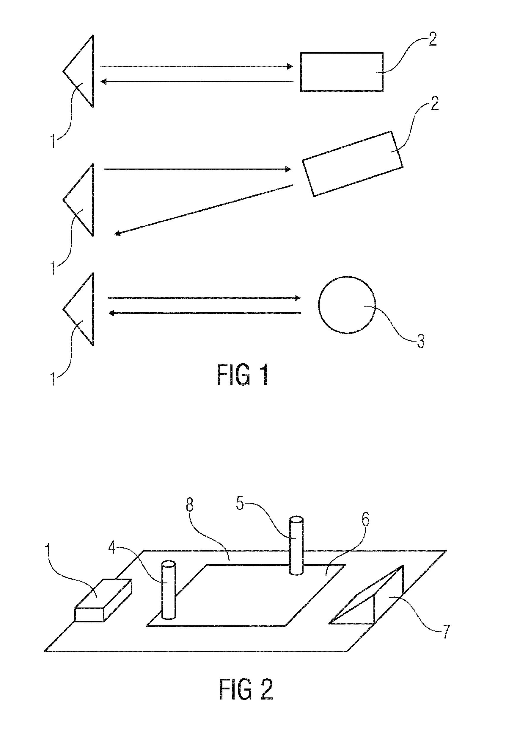
[0025]FIG. 1 shows, in the upper diagram, a schematic view of a transmitter / receiver 1 and a reflector 2 which has a planar reflection face. In the illustration of the upper figure, the reflector 2 assumes its precise position, with the result that the reflected beam runs parallel to the incident beam. Precise measurement of the ultrasonic propagation time is possible with this arrangement.

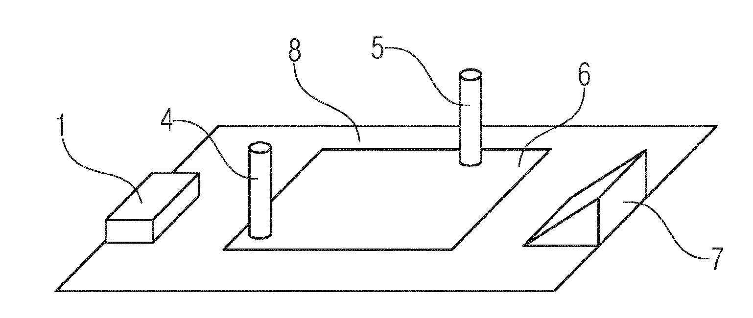
[0026]In the illustration of the middle diagram, the reflector 2 is rotated with respect to the position of the upper illustration. The reflected beam is therefore deflected and no longer impinges directly on the receiver, which entails severe screening of the signal. This effect does not occur with a bar reflector 3 which is present in the lower diagram in FIG. 1. With such a bar reflector 3 in the form of a standing cylinder there is no such angular dependence, since, as a result of the rotational symmetry of a cylinder, the geometric reflection range is identical from each angle at which the ra...


PUM


Abstract

The present disclosure describes a tank comprising an ultrasonic sensor, a first cylindrical reflector, and a second cylindrical reflector. The ultrasonic sensor may be disposed on the floor of the tank for measuring the signal propagation time through a liquid located in the tank and comprise a transmitter/receiver.

Description

CROSS-REFERENCE TO RELATED APPLICATIONS[0001]This application is a U.S. National Stage Application of International Application No. PCT / EP2014 / 070163 filed Sep. 23, 2014, which designates the United States of America, and claims priority to DE Application No. 10 2013 219 643.1 filed Sep. 27, 2013, the contents of which are hereby incorporated by reference in their entiretyTECHNICAL FIELD[0002]The present disclosure relates to a sensor for a liquid tank and more particularly to an ultrasonic sensor for a liquid tank.BACKGROUND[0003]During the measurement of propagation time by means of ultrasonic sound, an ultrasonic wave is emitted by a transmitter, passes through an indeterminate distance and subsequently impinges on the receiver. If the propagation speed and the distance from an object are known, the propagation time of the wave can be determined. Since the transmitter (e.g., an ultrasonic transducer) is a transmitter-receiver combination, the emitted sound wave must be reflected ...

Claims


Application Information

Patent Timeline
IPC IPC(8): G01F23/296G01N29/22
CPCG01F23/2962G01N29/223G01N29/221
Inventor STANGL, RONNYHEINRICH, STEPHANSCHAEDLICH, DENNY
Owner VITESCO TECH GMBH
Why Eureka
Try Eureka