Industrial hollow cathode

a hollow cathode and hollow cathode technology, applied in the field of hollow cathodes, can solve the problems of limiting the lifetime of hollow cathodes, the need to generate an electrical breakdown of ionizable working gas, and the tubular cathode of delcroix, etc., and achieves the effect of simple fabrication and us

Active Publication Date: 2010-06-01
KAUFMAN & ROBINSTON
View PDF4 Cites 4 Cited by
  • Summary
  • Abstract
  • Description
  • Claims
  • Application Information

AI Technical Summary

Benefits of technology

[0013]In light of the foregoing, it is a general object of the invention to provide a hollow cathode that is simple to fabricate and use, while having an operating life of at least several hundred hours using working gas contaminated with the typical impurities found in industrial applications.
[0015]Yet another general object of the invention is to provide a hollow cathode, with an operating lifetime of at least several hundred hours, that does not degrade significantly due to atmospheric exposure between periods of operation.
[0018]Still another specific object of the invention is to provide a hollow cathode that minimizes thermal losses by not having a continuous thermal conduction path between the dense internal plasma and the cooler cathode support.

Problems solved by technology

The ions bombarding surface 16B also cause erosion, thereby limiting the lifetime of hollow cathode 11.
The requirement for a voltage of at least several hundred volts results from the need to generate an electrical breakdown in the ionizable working gas.
The simple tubular cathode of Delcroix, et al., has a limited lifetime, typically a few tens of hours in the sizes and operating conditions of interest for ion sources.
While such a lifetime may be adequate for some applications, it is far too short for the electron emission functions of many industrial ion sources.
This degradation is believed due to the welding together of the shields, providing a direct thermal conduction path through those shields.
However, exposure to atmosphere rapidly degraded the electron emission characteristics of the emission material—see Zuccaro in AIAA Paper 73-1140, 1973.
The heat losses of the prior-art hollow cathode shown in FIG. 4 are again by radiation and conduction, but the heat loss paths are more complicated than those for the hollow-cathode shown in FIGS. 1 and 2 because of the more complicated construction.
However, there is another major heat loss path.
Reliability of resistive heater 27 has been an recurrent problem with both designs shown in FIGS. 4 and 5.
Repeated exposure of the foil insert to atmosphere, however, still results in embrittlement and flaking of the foil insert, with the flakes eventually plugging the central passage in the insert through which the ionizable working gas flows.
This failure is due to the formation of cracks in tube 61 that permit much of the working gas to escape before reaching opening 64, thus preventing the starting or normal operation of the hollow cathode.
To summarize the prior art of hollow cathodes, the simple tubular hollow cathode of Delcroix, et al., withstands exposure to atmosphere very well, but it has a very short lifetime.
The space electric-propulsion hollow cathodes, with an insert coated or impregnated with emissive material, can have extremely long lifetimes, but cannot withstand repeated exposure to atmosphere.
With repeated exposures, the foil insert also fails.
The absorption of hydrogen can cause embrittlement.
But that lack of failure was only due to the more rapid failure of the reactive emissive materials in inserts 32 and 42.
Without these emissive materials, those cathodes were unable to operate in the temperature range of 1400-1500 K for which they were designed.

Method used


Image

  • Industrial hollow cathode
  • Industrial hollow cathode
  • Industrial hollow cathode

Examples


Embodiment Construction

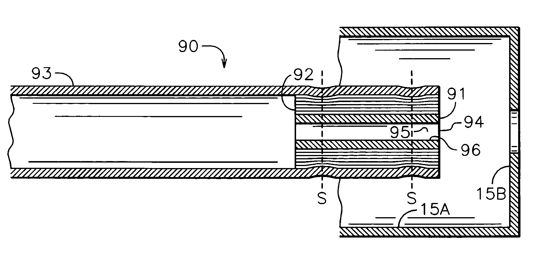
[0078]Referring to FIG. 11, there is shown an embodiment of the present invention. Hollow cathode 90 comprises refractory-metal first tube 91, which is surrounded by plurality of refractory-metal radiation shields 92, which in turn is surrounded by refractory-metal second tube 93. A radiation shield is defined herein as a single layer that circumferentially encloses the hollow-cathode tube. As described in the prior art, this definition is consistent with radiation heat transfer from layer-to-layer being much greater than conductive heat transfer along a spiral winding for the dimensions, temperatures, and foil used. A plurality of shields is therefore conveniently constructed as a spiral, multiple-turn winding of refractory-metal foil, or a plurality of such windings. In order to minimize the layer-to-layer contact between shields in a spiral winding, the metal foil may be textured before winding. The foil can textured by pressing it against a rough or corrugated surface, which imp...


PUM


Abstract

In accordance with one embodiment, the hollow cathode is comprised of a first tantalum tube, tantalum foil, and a second tantalum tube. The foil is in the form of a spiral winding around the outside of the first tube and is held in place by the second tube, which surrounds the foil. One end of the second tube is approximately flush with one end of the first tube. The other end of the second tube extends to a cathode support through which the working gas flows. To start the cathode, a flow of ionizable inert gas, usually argon, is initiated through the hollow cathode and out the open end of the first tube. An electrical discharge is then started between an external electrode and the first tube. When the first tube is heated to operating temperature, electrons are emitted from the open end of the first tube.

Description

CROSS-REFERENCE TO RELATED APPLICATION[0001]This application is based upon and claims benefit of Provisional Application No. 60 / 785,827 filed Mar. 25, 2006.FIELD OF INVENTION[0002]This invention relates generally to hollow cathodes, and more particularly it pertains to hollow cathodes used to emit electrons in industrial applications.BACKGROUND ART[0003]Hollow cathodes are used to emit electrons in a variety of industrial applications. As described in a chapter by Delcroix, et al., in Vol. 35 of Advances in Electronics and Electron Physics (L. Marton, ed.), Academic Press, New York (1974), beginning on page 87, there are both high and low pressure regimes for hollow-cathode operation. In the high-pressure regime, the background pressure (the pressure in the region surrounding the hollow cathode) approaches or exceeds 1 Torr (130 Pascals) and no internal flow of ionizable working gas is required for operation. In the low-pressure regime with a background pressure below 0.1 Torr, an i...

Claims


Application Information

Patent Timeline
Patent Type & Authority Patents(United States)
IPC IPC(8): H01J1/20
CPCH01J1/025
Inventor SHONKA, CHRIS M.KAHN, JAMES R.KAUFMAN, HAROLD R.
Owner KAUFMAN & ROBINSTON
Why Eureka
Try Eureka