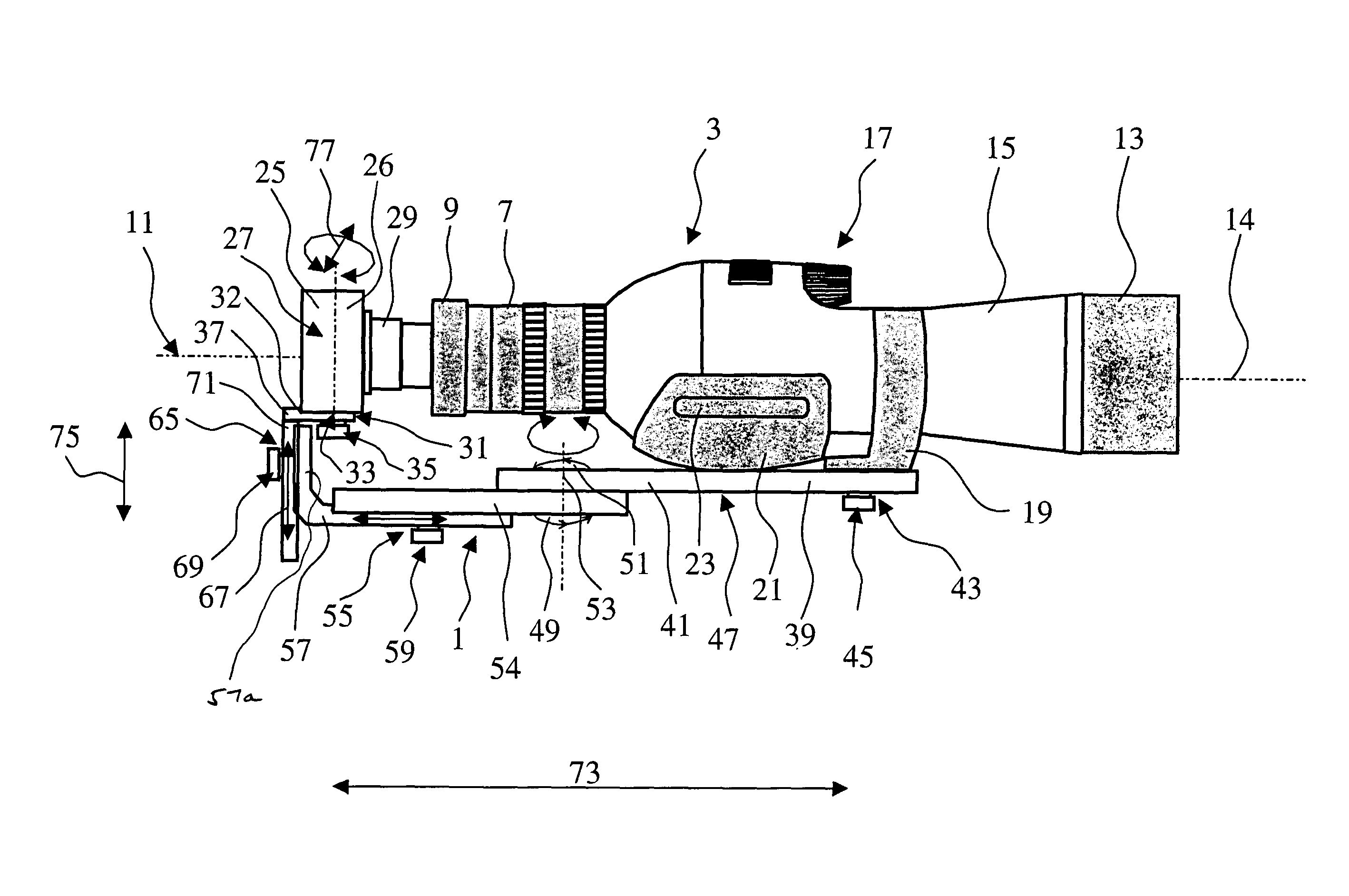
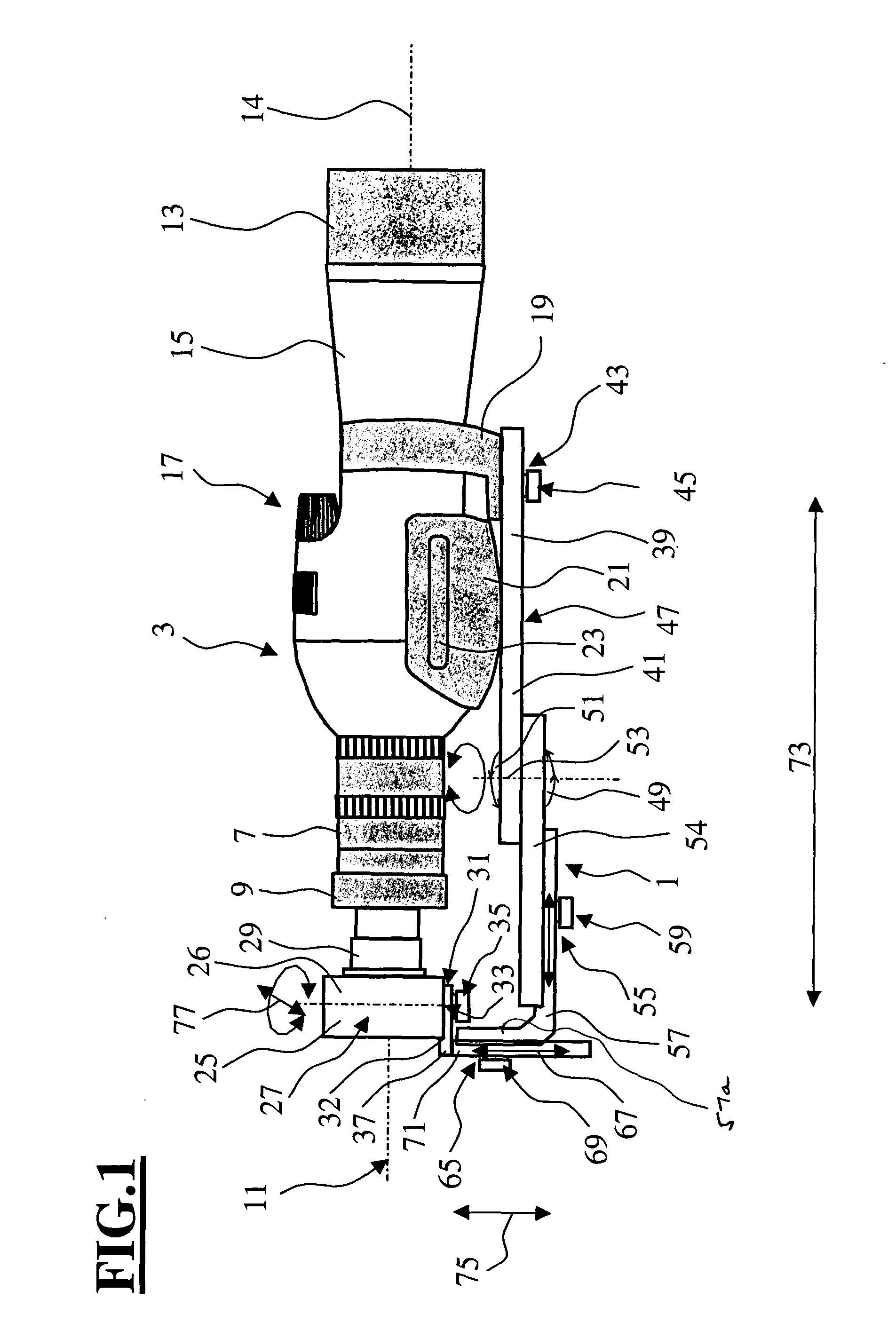
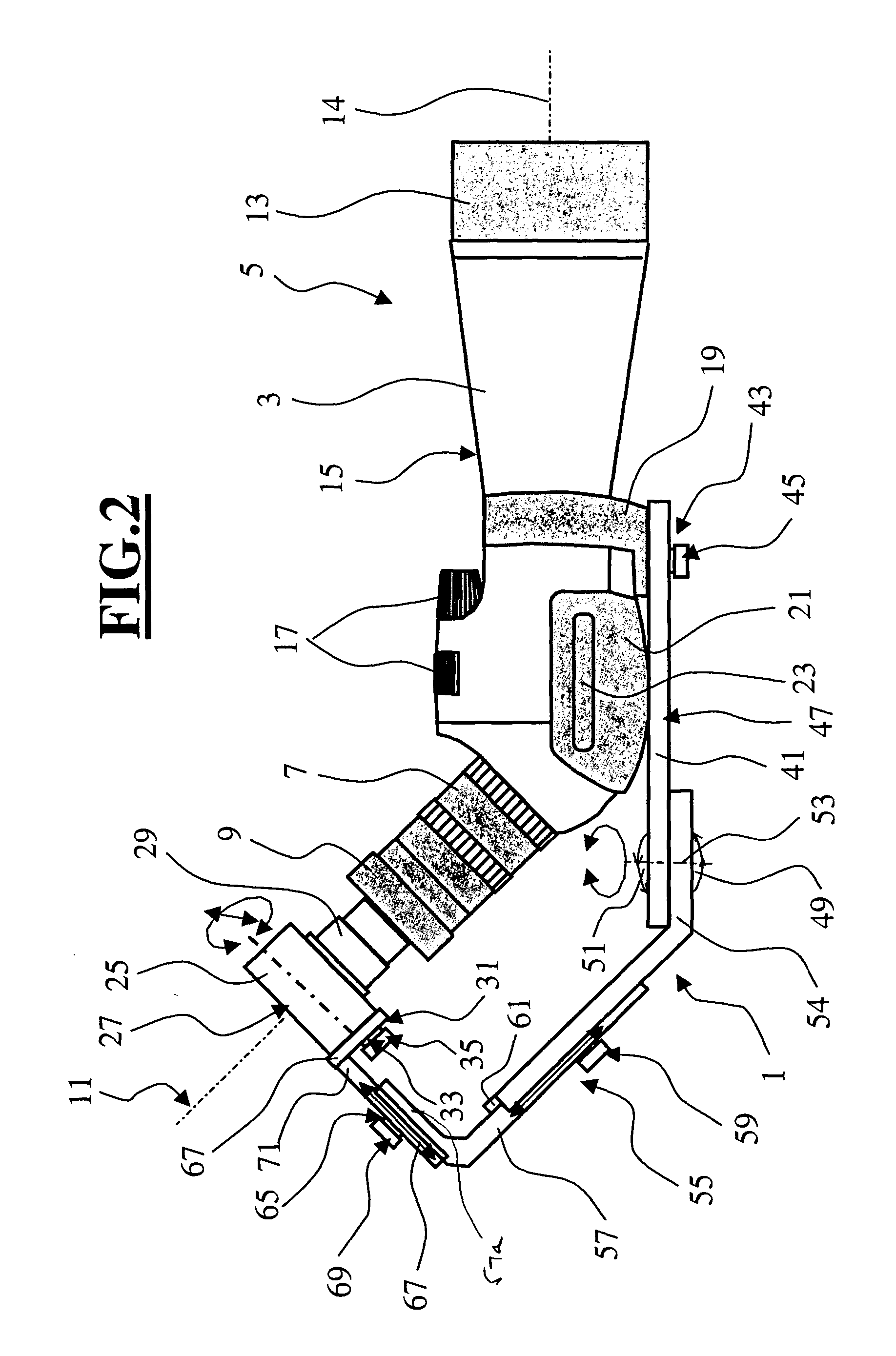
[0025] The glass 3 shown in FIG. 1 is a monocular and includes an ocular 7, an objective 13 and a housing 15. Furthermore, the monocular 3 has a focus drive 17. A grasping region 21 having grasping recesses 23 is arranged in the lower region of the monocular 3. The grasping recesses are preferably made of a rubber-like material. Furthermore, the monocular 3 includes an attachment element 19 for a stand or tripod. It is understood that the arrangement of FIG. 1 could be used also with a glass in form of a binocular.
[0026] The optics of the objective fix an optical axis 14 of the objective 13 and an optical axis 11 of the ocular 7 is fixed by the optical elements of the ocular 7. With the monocular 3 having linear viewing, the optical axes (11, 14) of the ocular 7 and objective 13 are coincident.
[0027] A base 39 is tightly connected to the attachment element 19 for a stand or tripod via an attachment device 43. In the embodiment shown, the base 39 is configured in the form of a base plate 41. The base 39 could, however, also have another shape, for example, it could be rod-shaped or angle-shaped.
[0028] In the embodiment shown, the connection between the base plate 41 and the attachment element 19 is provided by a clamp screw. However, a tight connection between the attachment element 19 and the base plate 41 could be provided especially by an element including clamping jaws. The attachment device 43 should be so configured that it can be again loosened so that the arrangement can be separated from the monocular 3. Attachment elements 19, as a rule, have a standardized form so that a tight connection can be provided between the attachment element 19 and the base 39. In most cases, this is done by means of a one-quarter inch clamp screw 45. A cutout (not shown) is provided in the base 39 so that the clamp screw 45 can pass through the base plate 41.
[0029] Several base attachment elements 47 for a stand or tripod are configured in the base plate 41. It can be especially provided that several threaded bores are configured in the base plate 41 so that this base plate 41 can be threadably fastened to a stand or tripod by means of a screw. The position at which the base plate is mounted on the stand can be so selected that it is possible to connect the base plate 41 to the stand so that the vertical of the center of gravity of the system (comprising camera, monocular and the arrangement) passes in the vicinity of one of the base attachment elements 47, however, this vertical preferably passes directly through the particular base attachment element 47 selected.
[0030] Base plate 41 is connected to a member 54 by means of a joint 49. A rotational joint 51 is provided as joint 49 and has a rotational axis 53 perpendicular to the optical axis of the monocular 3. With this arrangement of the rotational axis 53, the camera can be pivoted laterally away from the ocular 7. If the rotational axis 53 of the rotational joint 51 were parallel to the optical axis 11 of the ocular, then the camera could likewise be pivoted away from the ocular but the region behind the boundary surface of the ocular would not be entirely cleared. The boundary surface is delimited by the end edges of the ocular. It is especially advantageous when the region (which is formed by the perpendicular from the last user-end end point of the ocular 7 of the monocular 3) is cleared by pivoting away the camera.
[0031] For this reason, it is especially advantageous when the rotational axis 53 of the rotational joint 51 and the optical axis 11 of the ocular 7 conjointly define an angle. Furthermore, it is advantageous when the rotational axis 53 is disposed between the base attachment element 47 and the boundary surface of the ocular 7 of the monocular 3. In this way, it is ensured that the region rearward of the ocular is completely or almost completely cleared when the camera is pivoted.
[0032] In the embodiment shown, a rotational joint 51 is used with which, when a camera is pivoted to the right and pivoted to the left, there are three detent positions at a spacing of 45° starting from the position assumed behind the ocular. With a pivoting to the left, the free space on the right side of the monocular is held completely free so that a right handed person can actuate the focus drive without hindrance.
[0033] In lieu of the rotational joint, a ball joint can be provided by means of which the camera can be pivoted away from the ocular of the monocular. It has been shown to be especially advantageous when the rotational point of the joint lies approximately on the optical axis 11 of the ocular 7.
[0034] The rotationally-movable element 54 is releasably connected to a counter element 57 to make available a length setting 55 via a clamp element 59. By loosening the clamp element 59, the counter element 57 can be displaced relative to the rotationally-movable element 54. An adjustment in length of this kind can be provided, for example, by providing a slot in the counter element 57 of the length adjustment. An axial guide can be provided so that the counter element 57 can be shifted only in the longitudinal direction relative to the element 54. For example, a U-shaped element can be provided as the rotationally-movable element 54. The counter element 57 is then guided by the two legs of the U-shaped element. In a configuration of this kind, the counter element 57 can be pressed against the base of the U-shaped element by means of a clamp element 59 whereby a fixed clamping can be achieved.
[0035] If no axial guide is provided, then the joint can be omitted and the counter element 57 of the length adjustment can be pivoted to the side by loosening the clamp element 59. In an embodiment of this kind, a separate rotationally-movable element 54 is unnecessary.
[0036] The arrangement of the rotational joint 51 and the counter element 57 of the length adjustment can, of course, be configured in the opposite sequence.
[0037] The counter element 57 is configured as an angle element. A slide 67 is releasably and fixably connected to the second leg by means of a clamp element 69. The second leg is not connected to the rotationally-movable element 54. In this type of clamp connection by means of clamp element 69, the same system can be used as in the clamp connection by means of the clamp element 59. With the slide 67, the camera, especially the objective 29 thereof, can be adjusted in elevation relative to the ocular 7 of the monocular 3.
[0038] The slide 67 includes a camera mount 31 in the form of a base plate 32. This base plate 32 is part of the slide 67 configured as angle element 37. In the embodiment shown, the thread, which is configured in most cameras in the base of the camera housing, is used in order to attach the camera housing 26 and therefore the camera 25 fixedly to the base plate 32 by means of a screw 35. If the camera 25 does not have a thread of this kind, then an attachment by means of clamping jaws can be provided on the slide 67.
[0039] In an advantageous embodiment (not shown), a ball head of a ball joint can be attached to the camera either by means of clamping or by a threaded fastener and the ball head is journalled in a ball socket. The ball socket is fixedly connected to the slide joint. This ball socket is provided with a latching mechanism which is preferably in the form of clamping jaws. By means of the latching mechanism, a setting of the angle position of the camera and therefore of the joint can be latched. In this way, it is possible to use the embodiment of the arrangement shown in FIG. 1 also for a monocular with an inclined view. However, the angle element 37 is used with a longer or correspondingly long configured slide region.
[0040] The system shown in FIG. 2 includes a camera and a monocular and differs from the system shown in FIG. 1 only in that this monocular 3 has an inclined eye piece which is here at 45°. The rotationally-movable element 54 is configured angled for adapting the arrangement 1 to this angled eye piece.
[0041] In the following, only the differences of the embodiment shown in FIG. 2 compared to FIG. 1 are discussed. Furthermore, in this embodiment, an additional stop element 61 is provided so that, when loosening the clamp element 59 before pivoting the camera 25, the camera can be moved away from the ocular 7 of the monocular 3 in the direction of the optical axis 11 of the ocular 7 before the pivot movement is carried out. For setting the original position, the counter element 57 of the length adjustment 55 is again pushed up to the stop 61 and is fixed by means of the clamp element 59. It can also be provided to make possible pulling out of the camera 25 away from the ocular of the monocular 3 by a predetermined maximum distance against a spring force. The base position is again assumed with the relaxing of the force acting from the outside. This mechanism facilitates the pivoting away from the ocular and makes possible to minimize the distance between the last lens surface of the ocular 7 and the objective of the camera 29.
[0042] In order to minimize the incidence of light between the objective and the camera, the user can use an eye shield or eye cup provided the ocular 7 is so equipped. The user can also simply use a hand to shield the connecting location between the camera objective 29 and the ocular 7 of the monocular.
[0043] If the camera 25 is positioned with respect to the monocular, then the camera focuses automatically on the image, which is generated by the monocular, insofar as a focusing is carried out via the objective. Only in rare cases is a manual refocusing needed. If no autofocus camera is used, then the focusing has to be done manually. This arrangement of the invention is suitable to an equal extent for film cameras, digital cameras and video cameras.
[0044] By selecting the magnification to which the camera is adjusted, the image section, which is imaged by the camera, can be changed. In this way, the image section, which can be recorded by the camera, can be adapted to the image section imaged by the monocular.
[0045] In digital or video cameras, this adaptation can also be made by readjusting the recorded images. The edges, which disturb the image impression, can be removed.
[0046] It is understood that the foregoing description is that of the preferred embodiments of the invention and that various changes and modifications may be made thereto without departing from the spirit and scope of the invention as defined in the appended claims.