
Microfluidic titration apparatus

Inactive Publication Date: 2005-02-17
HEWLETT PACKARD DEV CO LP
View PDF39 Cites 14 Cited by
  • Summary
  • Abstract
  • Description
  • Claims
  • Application Information

AI Technical Summary

Problems solved by technology

It will be appreciated that the foregoing titration procedure is time consuming and therefore expensive, relatively complex, and prone to error.

Method used


Image

  • Microfluidic titration apparatus
  • Microfluidic titration apparatus
  • Microfluidic titration apparatus

Examples


Embodiment Construction

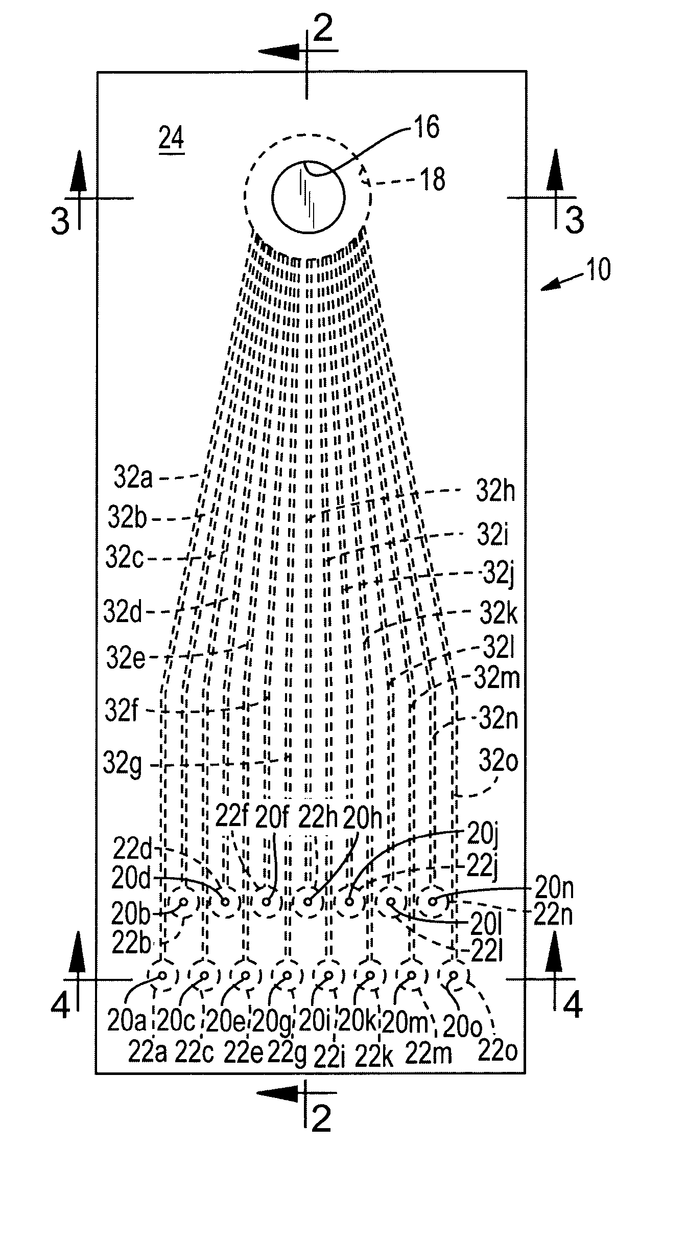
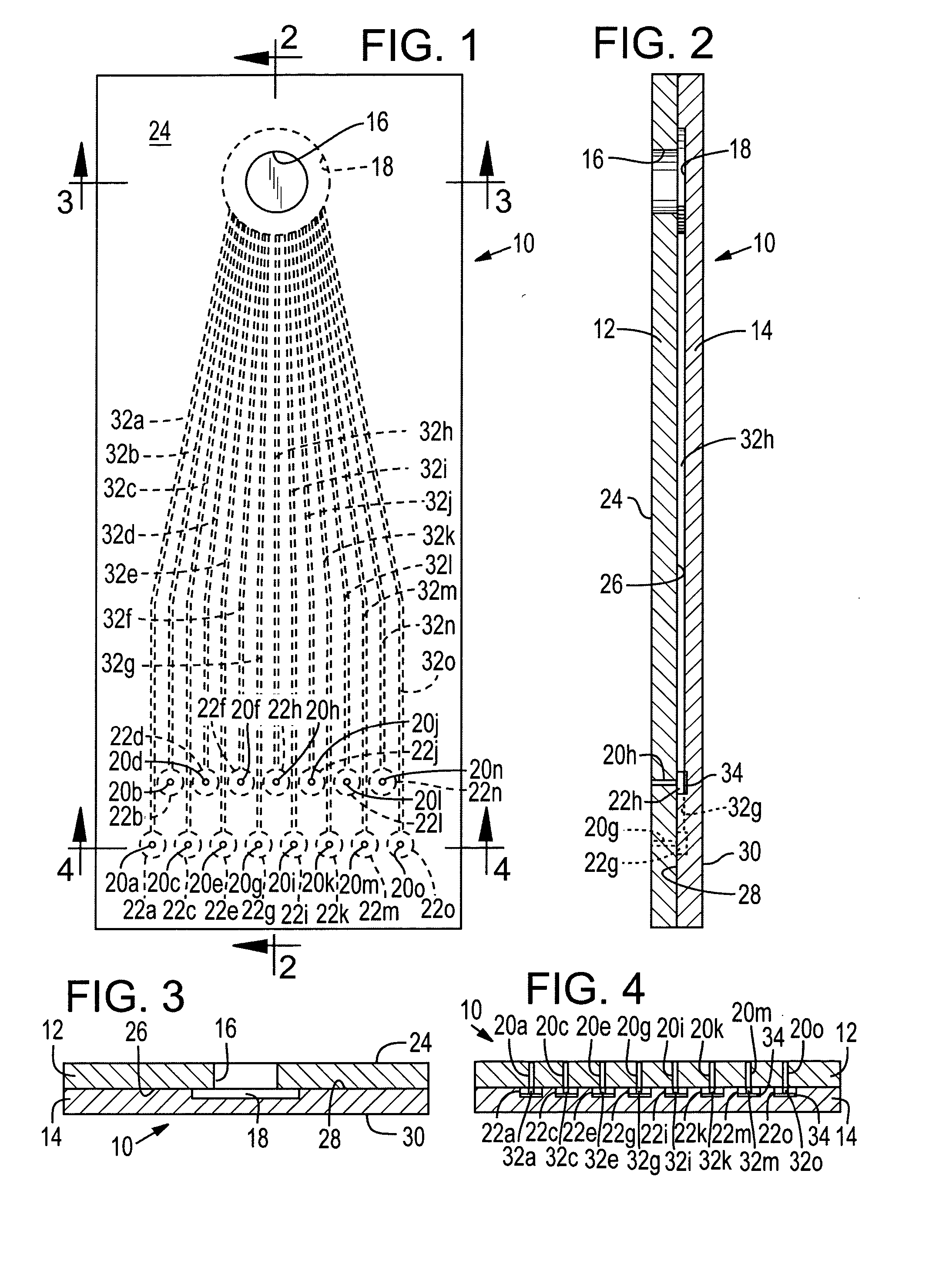
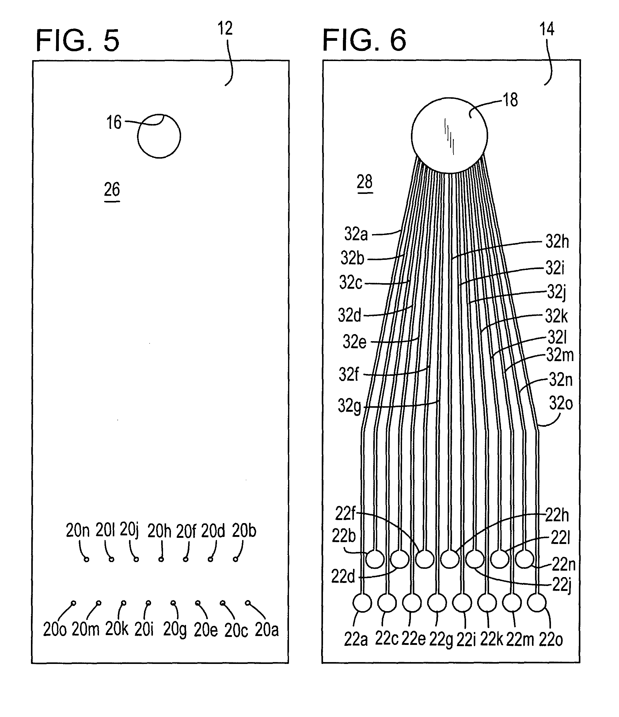
[0022] The illustrated invention provides an integrated, self-contained device for titrating a fluid sample. The invention facilitates introduction of a sample into the chip, routing the sample through a plurality of microfluidic channels into plural titration chambers by passive capillary action. Each of the titration chambers is preloaded with calibrated quantity of reagents and indicators, selected according to the specific kind of titration to be performed. Each of the titration chambers is ported to an air management chamber to facilitate passive capillary movement of sample fluid from the intake port, through the microfluidic channels and into the titration chambers. Any variety of titration analyses may be performed—depending upon the reagents and indicators preloaded into the titration chambers. While the inventive apparatus may be used in numerous situations, it is especially useful for field analysis of a water sample where more traditional sample collection and analytical...


PUM


Abstract

The illustrated invention defines an analytical titration chip comprising an optically transparent substrate such as glass or plastic that defines a fluid inlet port, plural microfluidic sample carrying channels communicating with the inlet, and plural titration chambers fluidly communicating with the channels. Each titration chamber contains a different concentration of the same titrant to define a spectrum or range of titrations. An air management chamber is in fluid communication with the titration chambers to facilitate capillary flow of fluid into the titration chambers.

Description

TECHNICAL FIELD [0001] This invention relates to apparatus for titrating fluid samples and more specifically, to an analysis chip having microfluidic sample handling channels and associated titration chambers for performing titration analysis of the sample. BACKGROUND OF THE INVENTION [0002] Titration is a commonly used chemical analytical procedure that is typically used to determine, for example, the concentration of a desired compound in a sample. There are of course many different procedures and techniques used to perform titration analyses. Nonetheless, stated simply, most titration methods involve the addition of measured increments of a standard solution (the “titrant”) to a sample solution to determine the stoichiometric equivalent point between the titrant and the sample. The titrant includes a known concentration of a compound that reacts with the sample in a known manner. The titrant may also include an indicator compound such as a dye that reacts when the compound in the...

Claims


Application Information

Patent Timeline
IPC IPC(8): B01L3/00G01N31/16G01N31/20G01N35/00G01N37/00
CPCB01L3/5027B01L2400/0406B01L2300/0864B01L2300/0816G01N21/79G01N35/00G01N37/00
Inventor HERNANDEZ, JUANTOM, DENNISCHEN, XIANGGINLARSON, GARYBLAIR, DUSTIN W.
Owner HEWLETT PACKARD DEV CO LP
Learn More