USB interface system

a technology of usb and interface system, which is applied in the field of usb (universal serial bus) interface system, can solve the problems of increasing the cost of the unit, and the inability to directly connect a peripheral with another peripheral through usb

Inactive Publication Date: 2005-02-17
TDK CORPARATION
View PDF5 Cites 70 Cited by
  • Summary
  • Abstract
  • Description
  • Claims
  • Application Information

AI Technical Summary

Benefits of technology

[0019] Further, preferably, a connection can be easily established between the host and the device, instead of using a cable.

Problems solved by technology

As mentioned above, however, it is impossible to directly connect a peripheral with another peripheral through USB.
Accordingly, there is a problem of increasing the cost of the unit.

Method used


Image

  • USB interface system
  • USB interface system
  • USB interface system

Examples


Embodiment Construction

[0031] Hereinafter, preferred embodiments of the invention will be described in detail referring to the accompanying drawings.

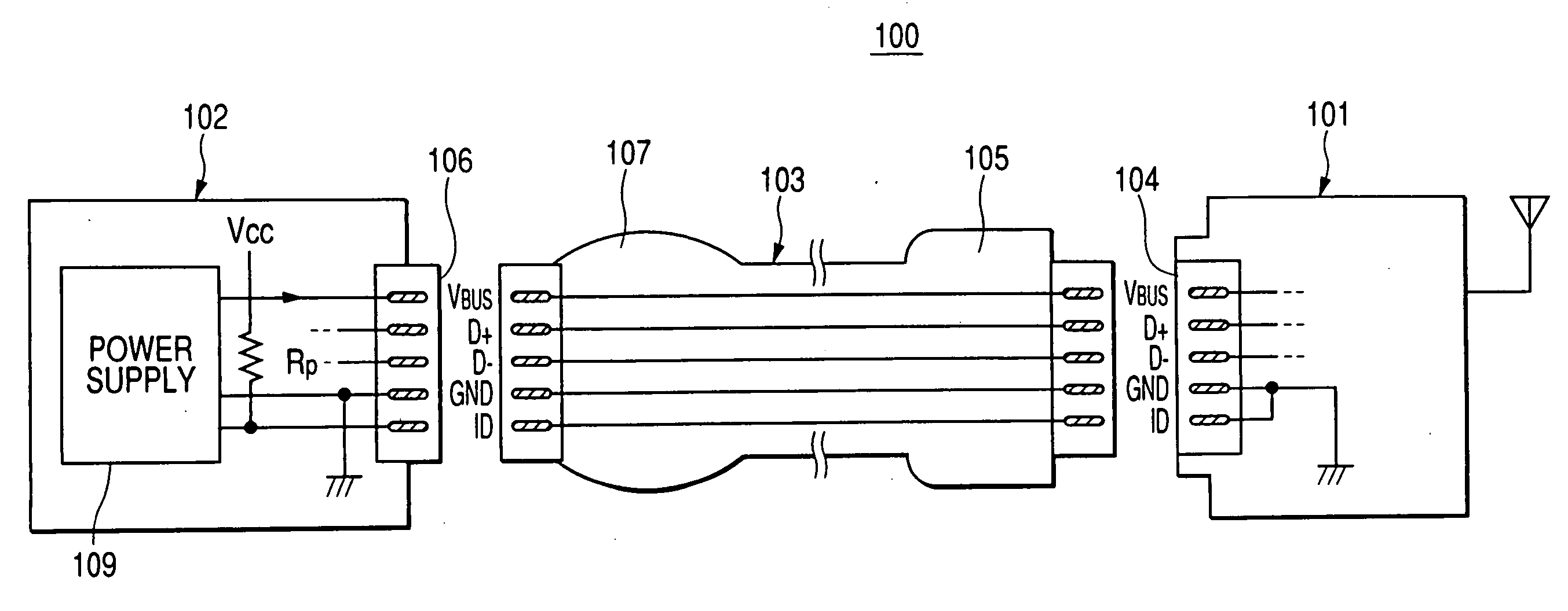
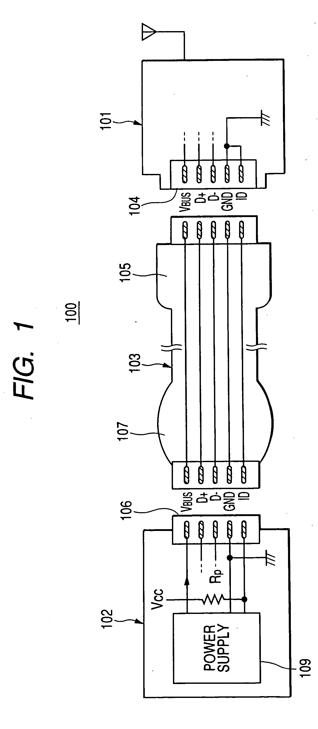
[0032]FIG. 1 is a schematic view showing the structure of a USB interface system according to one preferred embodiment of the invention.

[0033] As illustrated in FIG. 1, this system comprises a peripheral 101 (hereinafter, referred to as a host) serving as a USB host, a unit 102 (hereinafter, referred to as a device) serving as a USB device, and a USB cable 103 for connecting them.

[0034] In the invention, power supply is assumed from the device to the host, and the host 101 and the device 102 are the units having USB interfaces for the portable devices of low ability of power supply such as digital cameras, portable phones, and PDAs, and electric devices having AC power such as printers, faxes, scanners, and handy storages. Especially, this embodiment shows the case where the host is a “wireless LAN adapter” and the device is a “digital camera”. By connecti...


PUM


Abstract

When a host 101 is connected to a device 102 via a USB cable 103, the ID terminal on the device 102 is short-circuited to the GND line, hence to reduce the voltage level of the ID terminal. Since power feeding means 109 starts feeding power to the VBUS terminal when detecting that the voltage level of the ID terminal turns from “H” to “L”, the power is supplied to the host 101 through the VBUS line of the USB cable 103.

Description

BACKGROUND OF THE INVENTION [0001] The present invention relates to a USB (Universal Serial BUS) interface system, and more particularly to a USB interface system and a device capable of supplying power from the device to a host. [0002] USB is widely used as a general-purpose interface. USB is the standard standardized by the USB-IF (USB Implementers Forum) and it is a serial bus interface for connecting a host device such as a personal computer to a peripheral devise such as a mouse and a keyboard. At present, USB is mounted in almost all the personal computers and they can be connected to any peripheral device if only having a USB terminal. USB includes two standards: USB 1.1 capable of transferring data in a low speed mode (1.5 Mbps) or in a full speed mode (12 Mbps) and USB 2.0 capable of transferring data at a high speed in a high speed mode (480 Mbps) in addition to the above-mentioned two modes. If USB 2.0 is employed, even a digital video can be connected to a computer. [000...

Claims


Application Information

Patent Timeline
Patent Type & Authority Applications(United States)
IPC IPC(8): G06F1/26G06F13/40H04N5/225H04N101/00
CPCG06F13/409G06F1/266
Inventor OKAYASU, KAORU
Owner TDK CORPARATION
Why Eureka
Try Eureka