Rotor desiccant air-conditioning system for a motor vehicle

Inactive Publication Date: 2005-02-24
CHANT EILEEN
View PDF5 Cites 14 Cited by
  • Summary
  • Abstract
  • Description
  • Claims
  • Application Information

AI Technical Summary

Benefits of technology

[0017] 5. If the system is so designed, the additional dehumidification capability provided by the desic

Problems solved by technology

In addition, upon failure, the system performance changes are expected to be small since the

Method used


Image

  • Rotor desiccant air-conditioning system for a motor vehicle
  • Rotor desiccant air-conditioning system for a motor vehicle
  • Rotor desiccant air-conditioning system for a motor vehicle

Examples


Embodiment Construction

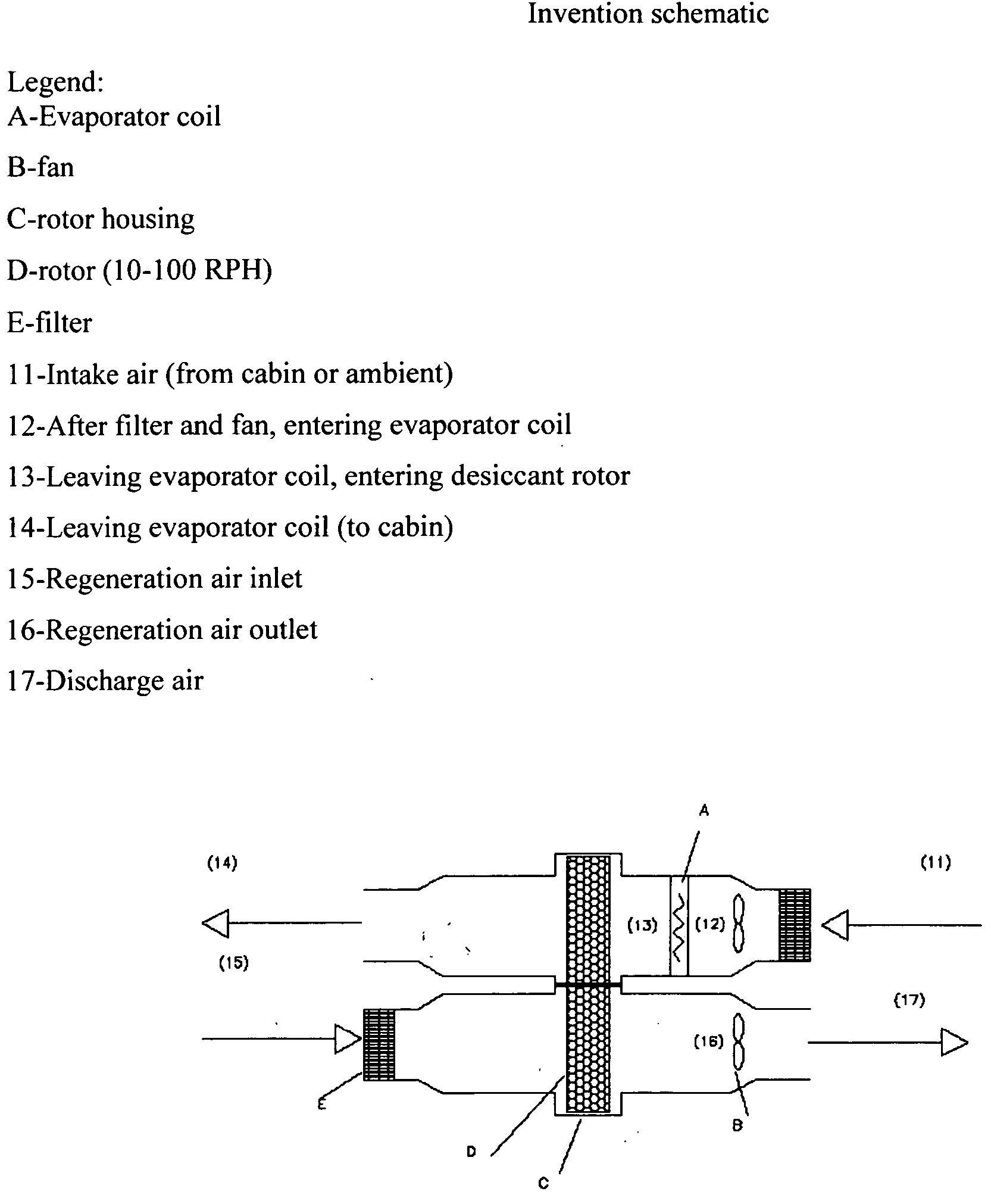
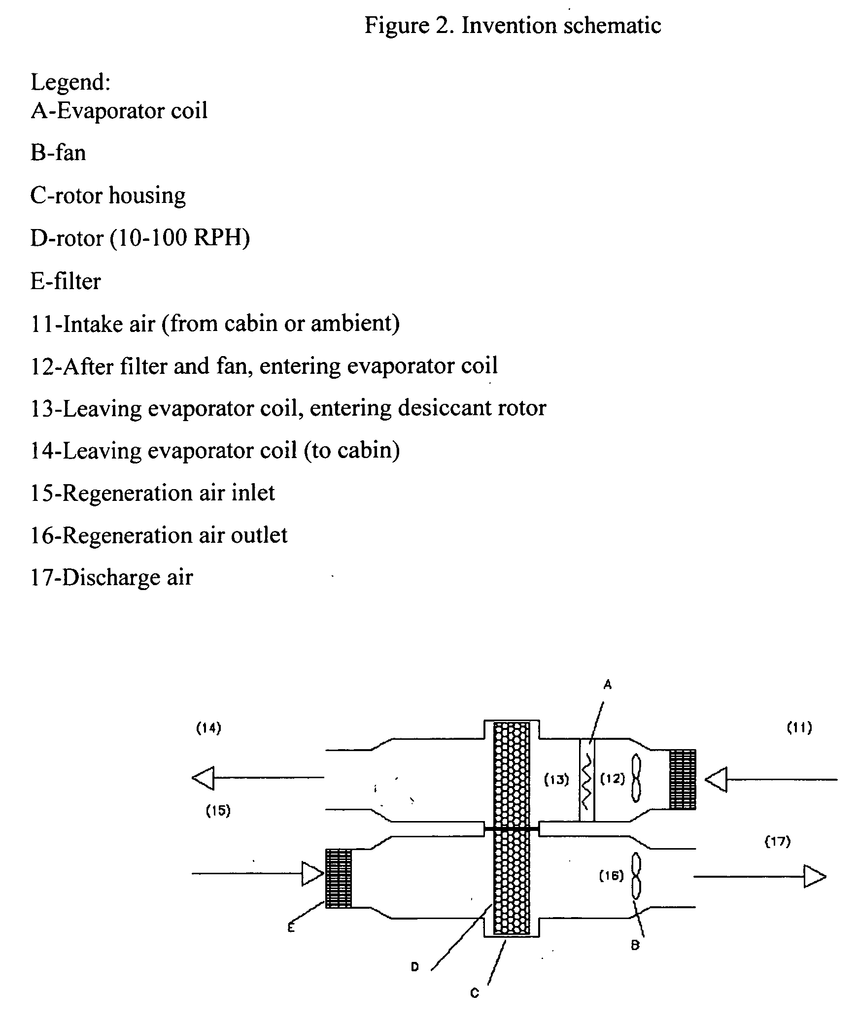
[0026]FIG. 2 is an illustration of the configuration of the invention where the desiccant rotor is downstream of the evaporator coil. The air being processed passes through the filter, the fan, and the evaporator coil where the air is cooled and dehumidified, then through the desiccant rotor where the air is dried and heated.

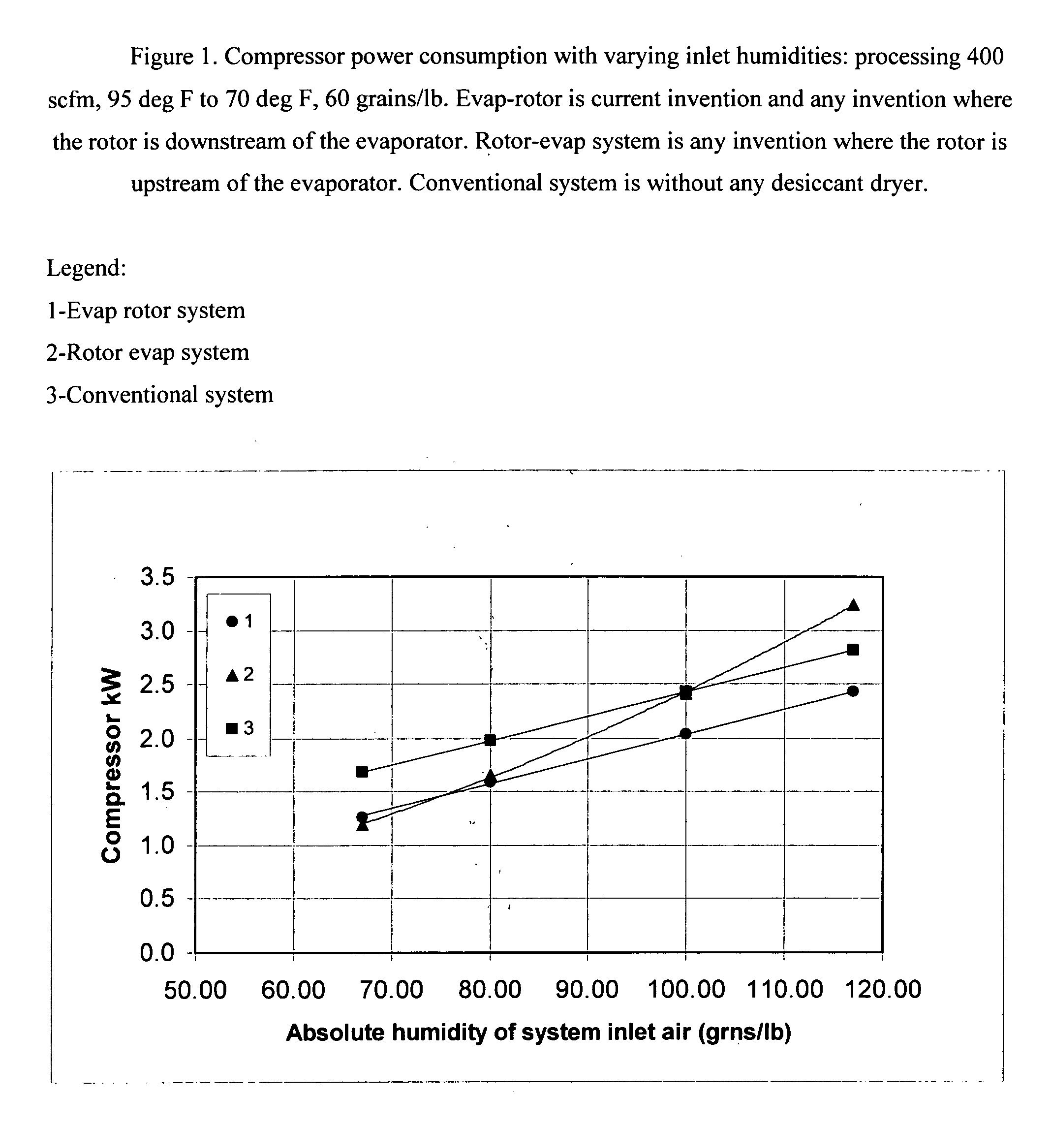
[0027] An analysis was performed on the configuration of this invention (evap-rotor) vs. a configuration where the desiccant is placed upstream of the evaporator (rotor-evap).

[0028] A model developed by Chant and Jeter (1995) for rotary desiccant wheels was used to simulate the desiccant rotor. In addition to the validation performed on the model described in the paper, the model was adapted to the Engelhard HexCore rotor and validated with data collected at the National Renewable Energy Laboratory in 1998. The model's latent capacity predictions for HexCore's hexagonal passage, Nomex core coated with titanium silicate desiccant were within + / −10% and the outl...


PUM


Abstract

An air-conditioning system for a cabin of a motorized vehicle comprising of an evaporator and desiccant, where said desiccant is downstream of evaporator, and said desiccant is a rotor that uses nearby excess heat to regenerate the desiccant.

Description

BACKGROUND [0001] This invention relates to dehumidification and cooling in an enclosed area, in particular, a method and system for climate control in a motorized vehicle. BACKGROUND OF THE INVENTION—DESCRIPTION OF PRIOR ART [0002] This invention relates to dehumidification and cooling in an enclosed area, in particular, a method and system for climate control in a motorized vehicle. There exists a strong need for dehumidification in the enclosed area of a motor vehicle; for safety reasons, i.e. the windshield can fog up during high humidity conditions, resulting in reduced driver visibility; comfort of the passengers; and if the humidity of the cabin can be lowered by thermally activated means, the compressor power consumption and the size of the direct expansion (DX) air-conditioning system can be reduced. If the load on the DX system is reduced through addition of a light component (i.e. a small desiccant rotor), the benefits include; fuel savings, reduced shaft horsepower requi...

Claims


Application Information

Patent Timeline
IPC IPC(8): B60H3/02B60H3/06F24F3/14
CPCB60H3/024B60H3/0633B60H2003/028F24F2203/1084F24F2203/1032F24F2203/1056F24F2203/1068F24F3/1423
Inventor CHANT, EILEEN
Owner CHANT EILEEN
Why Eureka
Try Eureka