Permanent-magnet rotor for an inner rotor type electric rotary machine and magnet-saving type rotor for a synchronous motor

a technology of permanent magnet rotor and inner rotor, which is applied in the direction of dynamo-electric machines, magnetic circuit rotating parts, and magnetic circuit shape/form/construction, etc., can solve the problems of affecting the operation of the motor, the motor size or weight will increase inevitably, and the motor performance will deteriorate, so as to suppress the increase of motor size and weight, the effect of easy magnetization

Inactive Publication Date: 2005-02-24
DENSO CORP
View PDF19 Cites 35 Cited by
  • Summary
  • Abstract
  • Description
  • Claims
  • Application Information

AI Technical Summary

Benefits of technology

[0011] In view of the above-described problems of the prior art, the present invention has an object to provide a permanent-magnet rotor for an inner rotor type electric rotary machine which is easy to magnetize and is capable of suppressing increase of motor size and weight in the case that the permanent magnets are installed closely to the outer cylindrical surface of the rotor core.

Problems solved by technology

However, the motor performance will deteriorate.
The motor size will increase inevitably.
As a result, the motor size or weight increases inevitably.
However, the rare-earth materials are expensive.
However, it is generally difficult to realize a thin magnet having the thickness less than approximately 2 mm from the restrictions in manufacturing processes of magnets and also from the requirements for assuring sufficient mechanical strength of magnets.
Furthermore, although the permanent magnets are installed into insertion holes of the rotor extending in the axial direction, this installation work is not easy in the case that the permanent magnets are magnetized beforehand.
This makes it difficult to uniformly magnetize the permanent magnets in the radial direction.
Furthermore, the structure of a required magnetizing apparatus will become complicated.

Method used


Image

  • Permanent-magnet rotor for an inner rotor type electric rotary machine and magnet-saving type rotor for a synchronous motor
  • Permanent-magnet rotor for an inner rotor type electric rotary machine and magnet-saving type rotor for a synchronous motor
  • Permanent-magnet rotor for an inner rotor type electric rotary machine and magnet-saving type rotor for a synchronous motor

Examples


first embodiment

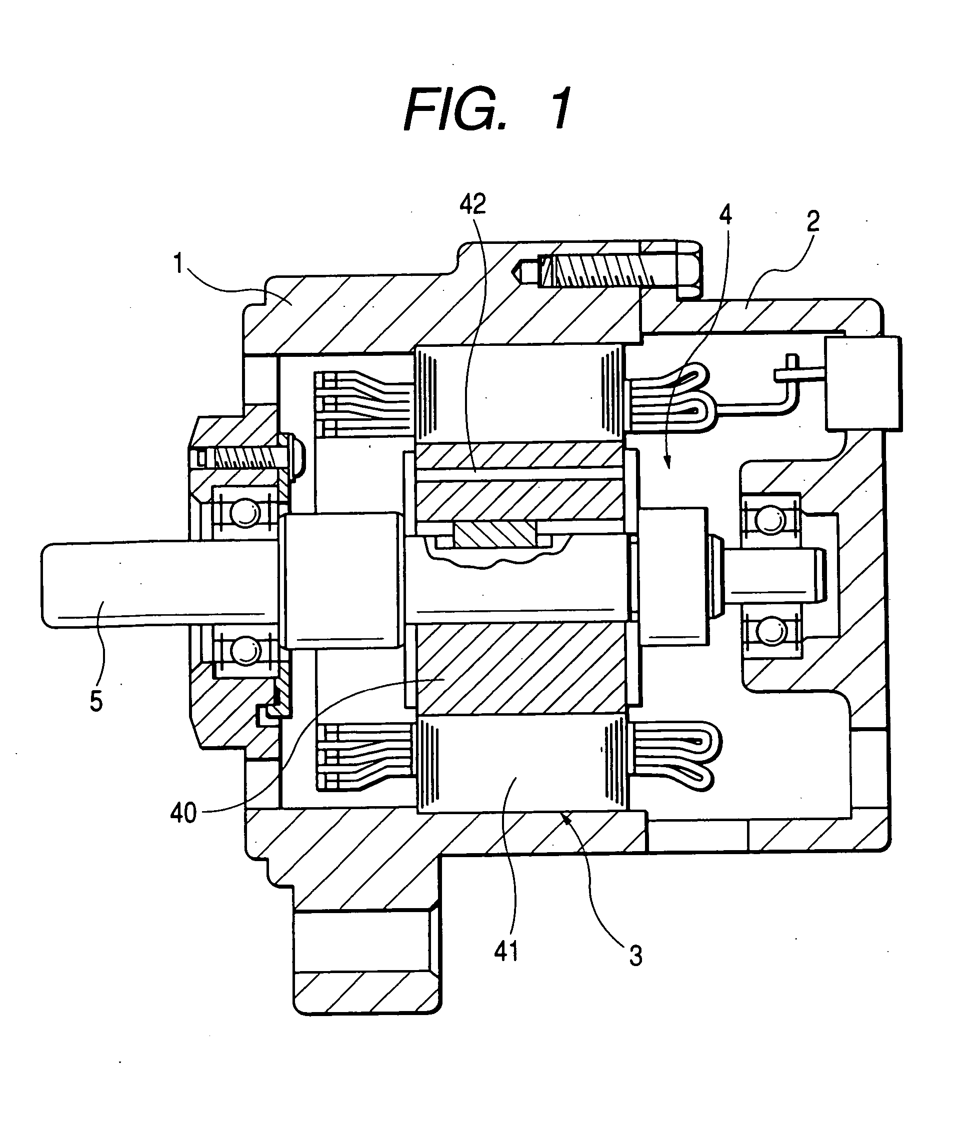
[0077]FIG. 1 shows an inner rotor type IPM constituting a 6-pole three-phase synchronous motor.

[0078] A front housing 1 and a rear housing 2 are connected securely with tightening bolts. A stator 3 is fixed on an inner cylindrical surface of the front housing 1. A rotor 4 is accommodated at a radial inner side of the stator 3. The rotor 4 is securely fixed around a rotor shaft 5. The rotor shaft 5 is supported by the housings 1 and 2 via bearings. The rotor 4 includes a rotor core 40 made of multilayered electromagnetic steel plates and permanent magnets 42 installed in magnet insertion holes 41 of this rotor core 40.

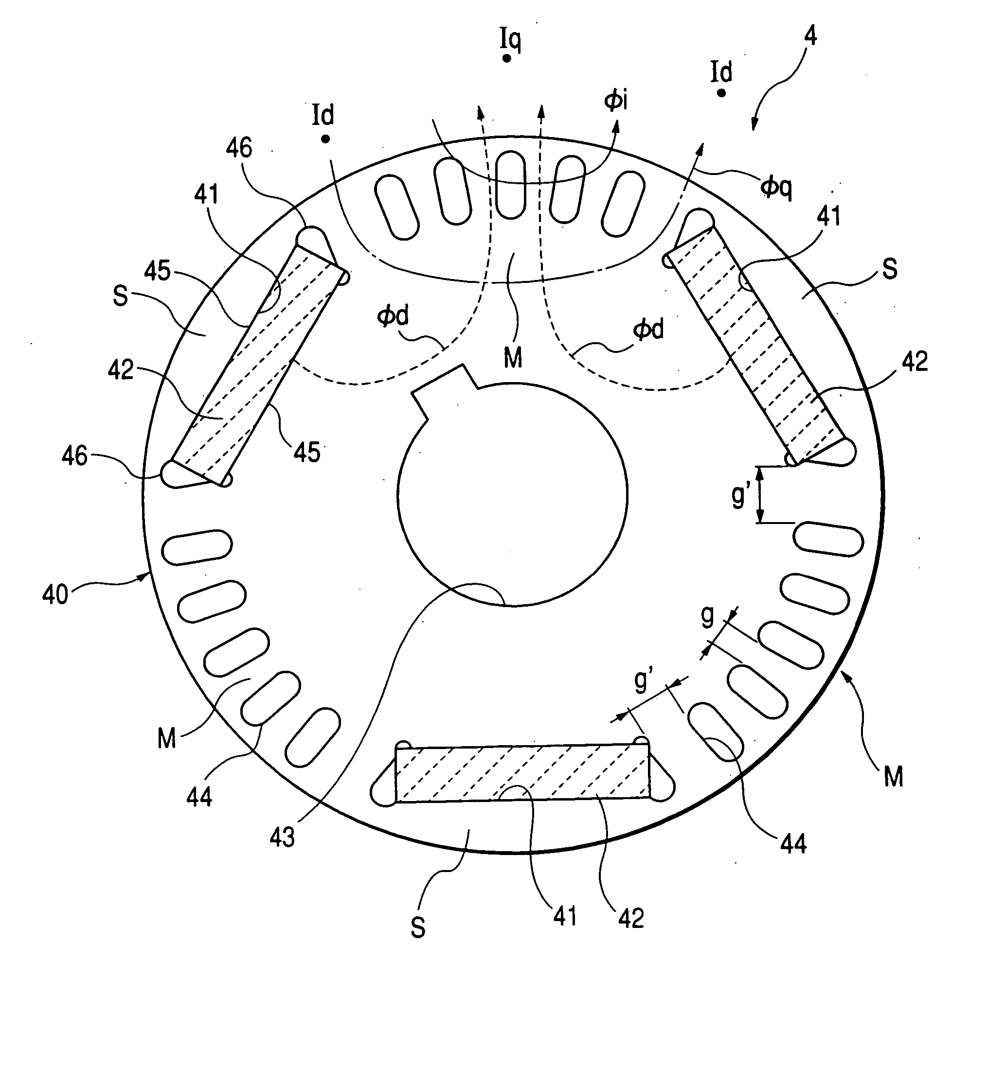
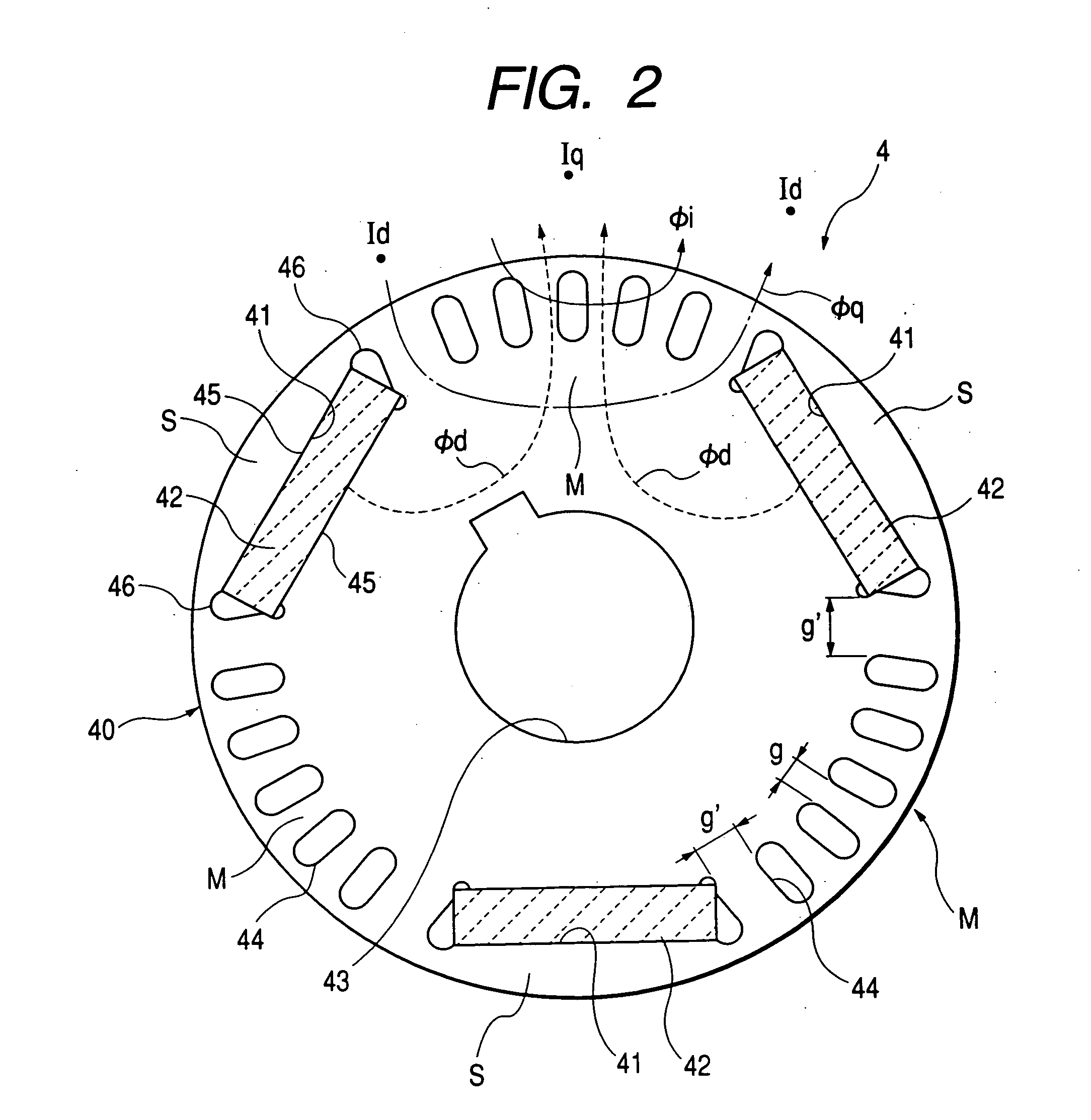
[0079]FIG. 2 is a cross-sectional view of the rotor 4 taken along a plane normal to the axis of the rotor 4, although a hatching showing the cross section of rotor core 40 is omitted. In addition to the above-described magnet insertion holes 41, the rotor core 40 has a rotary shaft hole 43 extending in the axial direction into which the rotor shaft 5 is inserted by pr...

second embodiment

[0093] A second embodiment of the present invention is different from the above-described embodiment only in that the vacant holes 44 are provided with a basket type wiring formed by aluminum die-cast. This makes it possible to suppress the generation of induction torque and prevent the motor from going into a disordered or non-synchronous condition. Although, additionally providing the basket type wiring is conventionally known, there was severe spatial restriction in installing this kind of wiring because an available space is limited to a narrow region between the magnet insertion holes 41 and the outer cylindrical surface of the rotor core 40. The magnet path resistance of the magnet flux was large. On the other hand, according to this embodiment, the basket type wiring is easily installed in a wide region where the magnet insertion holes 41 are omitted. Thus, this embodiment solves the conventional problem.

[0094] Third Embodiment

[0095]FIG. 3 shows a modified permanent-magnet ...

fourth embodiment

[0097] A magnet-saving type rotor for a synchronous motor in accordance with a fourth embodiment will be explained with reference to FIG. 4.

[0098] The magnet-saving type rotor shown in FIG. 4 includes a rotor core 101 made of soft iron and a total of three permanent magnets 102 made of rare-earth magnet. The rotor core 101 includes the same number of (i.e., three) permanent magnet accommodation holes 103 for separately accommodating the permanent magnets 102. Respective permanent magnet accommodation holes 103 extend in an axial direction of the rotor core 101 and are disposed at equal angular pitches of 120°. Furthermore, the rotor core 101 includes a total of six vacant holes (i.e., magnet-less holes) 104 for accommodating no permanent magnets. Respective vacant holes 104 extend in the axial direction of the rotor core 101 and are positioned continuously at both circumferential ends of respective magnet accommodation holes 103. The vacant holes 104 are continuously or integrally ...


PUM


Abstract

A total of three permanent magnets, installed in a rotor core closely to an outer cylindrical surface of the rotor core, are disposed at predetermined angular pitches in the circumferential direction of the rotor core. All of the permanent magnets are magnetized in such a manner that the direction of magnetization is the same when seen in the radial direction. A plurality of magnet-less holes, extending in the axial direction in the vicinity of the outer cylindrical surface of the rotor core, are provided between two adjacent permanent magnets.

Description

BACKGROUND OF THE INVENTION [0001] 1. Field of the Invention [0002] The present invention relates to a permanent-magnet rotor for an inner rotor type electric rotary machine and a magnet-saving type rotor for a synchronous motor. [0003] 2. Description of the Background Art [0004] The surface permanent-magnet motors (SPM) and the interior permanent-magnet motors (IPM) are two representative conventional synchronous machines using permanent-magnet rotors. The latter is advantageous in that mechanical support of the permanent magnets is easy and a reluctance torque can be obtained in addition to a magnetic rotor. [0005] In the conventional IPM, permanent magnets are installed in a rotor core closely to an outer cylindrical surface thereof and disposed at equal pitches. The permanent magnets are magnetized to have alternate polarities in the circumferential direction. [0006] Furthermore, switched reluctance motors (SRM) and synchronous reluctance motors (SYNRM) are also conventionally k...

Claims


Application Information

Patent Timeline
Patent Type & Authority Applications(United States)
IPC IPC(8): H02K1/27H02K21/14
CPCH02K1/2746H02K21/14H02K2213/03
Inventor ASAI, JIROOGAWA, SHINICHI
Owner DENSO CORP
Why Eureka
Try Eureka