
Security tag with three dimensional antenna array made from flat stock

a technology of antenna array and security tag, which is applied in the field of security tags, can solve the problems of reducing marketability and adding manufacturing expens

Inactive Publication Date: 2005-02-24
CHECKPOINT SYST INC
View PDF45 Cites 105 Cited by
  • Summary
  • Abstract
  • Description
  • Claims
  • Application Information

AI Technical Summary

Benefits of technology

The patent describes an antenna configuration for a security tag that optimizes the reception of signals from an interrogator or reader. The antenna consists of three dipoles arranged in a non-parallel nor collinear configuration, with one dipole positioned out of the plane formed by the other two dipoles. The method of fabricating the antenna involves forming the dipoles on a web material, cutting the material to free a portion of the third dipole, and displacing it out of the material. The technical effect of this configuration is improved signal reception for security tags.

Problems solved by technology

However, both of the aforementioned approaches results in a larger tag, adding manufacturing expense and reducing marketability.

Method used


Image

  • Security tag with three dimensional antenna array made from flat stock
  • Security tag with three dimensional antenna array made from flat stock
  • Security tag with three dimensional antenna array made from flat stock

Examples


Embodiment Construction

[0021] It will be appreciated by those skilled in the art that changes could be made to the embodiments described above without departing from the broad inventive concept thereof. It is understood, therefore, that this invention is not limited to the particular embodiments disclosed, but it is intended to cover modifications within the spirit and scope of the present invention as defined by the appended claims.

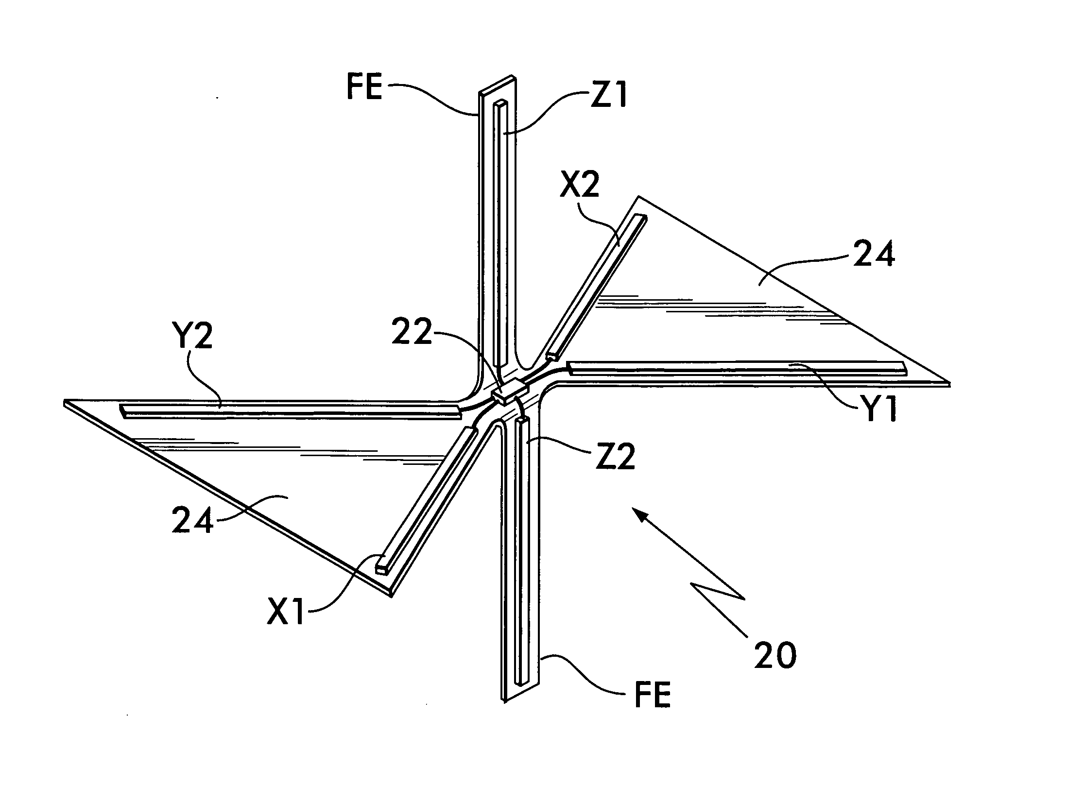
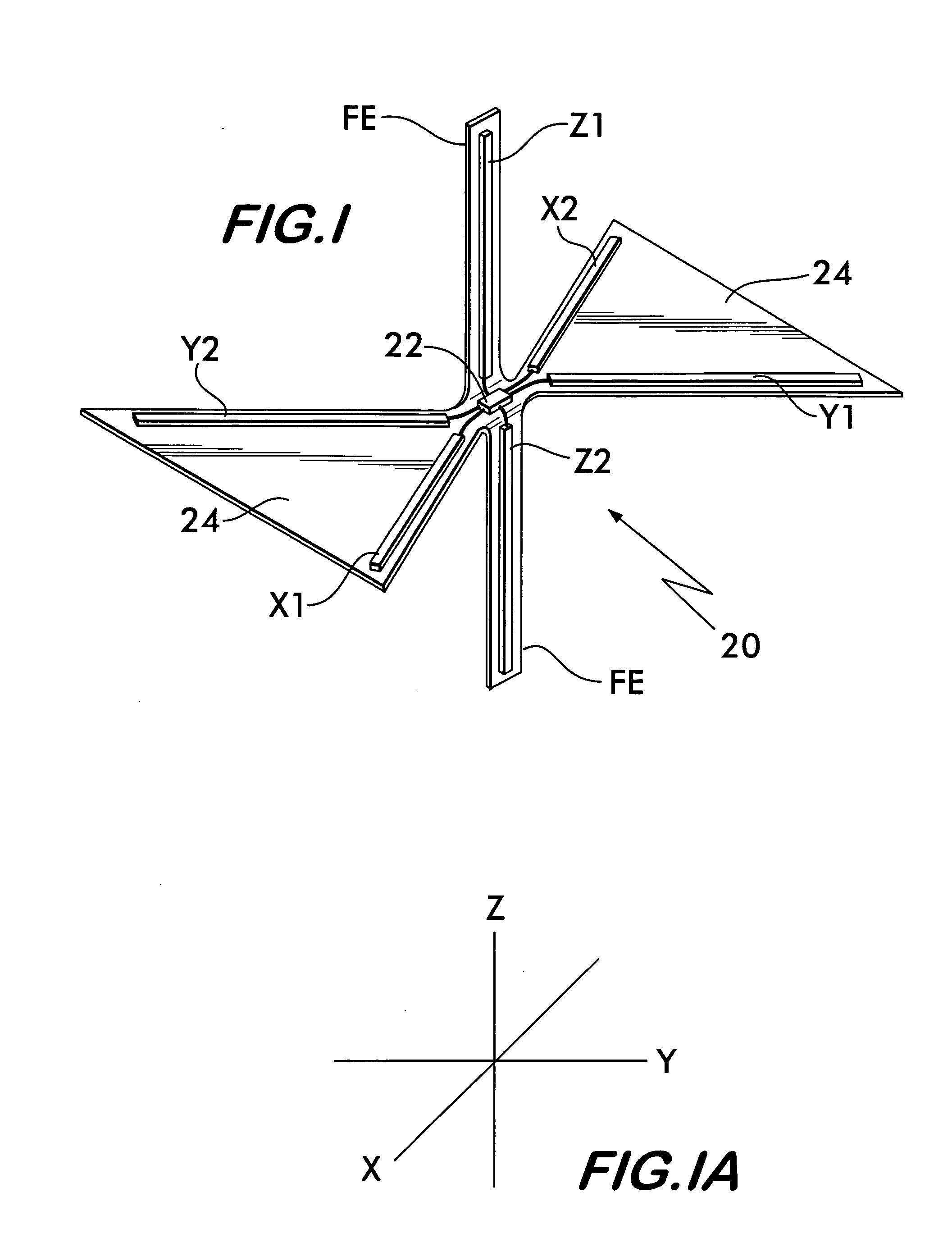
[0022] There is shown at 20 in FIG. 1 an RFID security tag comprising a three-dimensional antenna. The RFID security tag 20 comprises three dipole antennae coupled to an RFID integrated circuit (IC) 22. A dipole antenna in the x-axis (see FIG. 1A for axes orientation) comprises antenna stubs X1 and X2. A dipole antenna in the y-axis comprises antenna stubs Y1 and Y2. Finally, a third dipole antenna in the z-axis comprises antenna stubs Z1 and Z2. This RFID security tag 20 can be packaged in an enclosure, e.g., a ball-shaped enclosure, a cubic box-shaped enclosure, etc. The RF...


PUM


Abstract

A three-dimensional dipole antenna system for an RFID tag that optimizes detection for a given available volume in which to situate the RFID tag.

Description

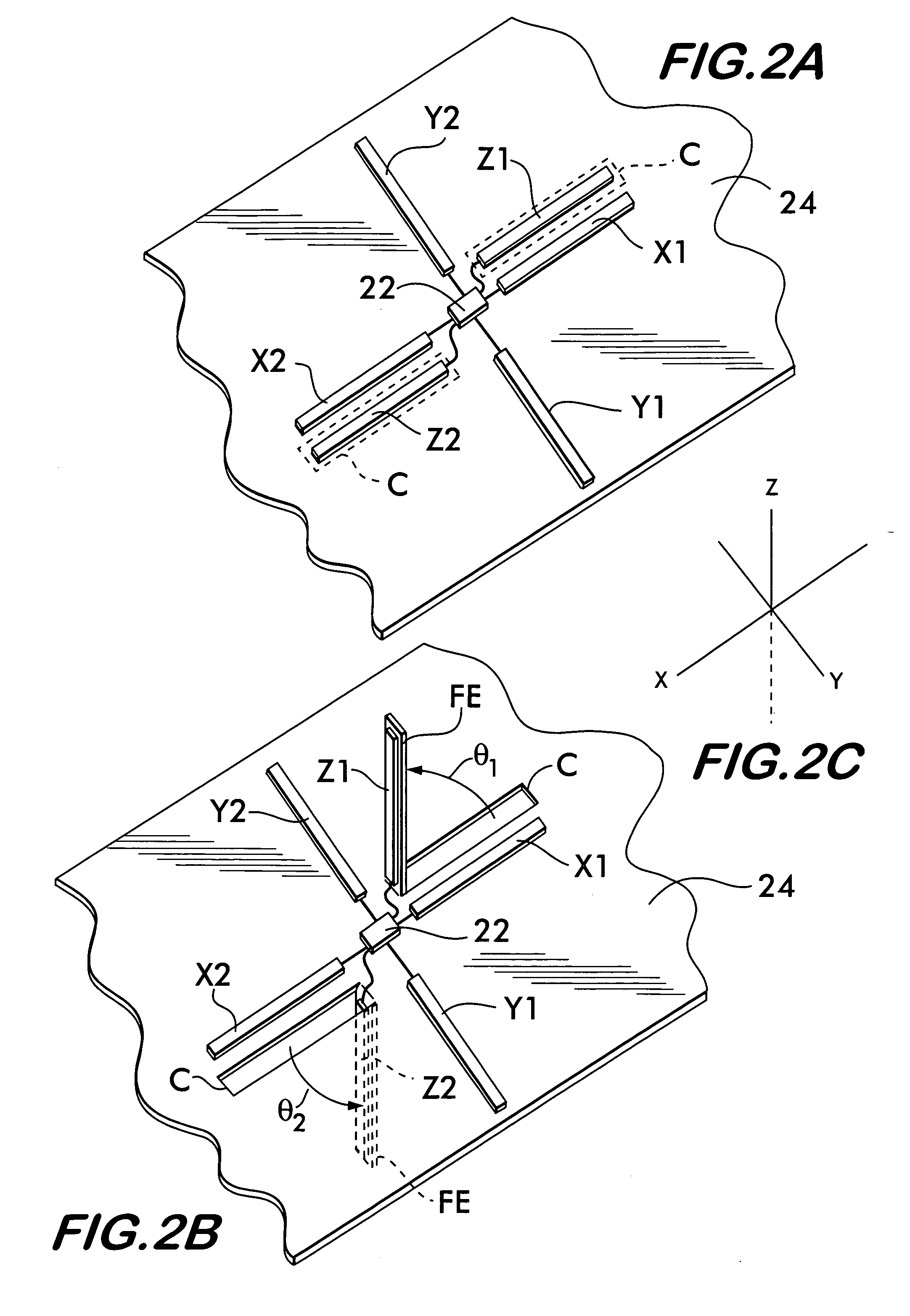
BACKGROUND OF THE INVENTION [0001] 1. Field of Invention [0002] This invention relates to security tags and, more particularly, to an ultra-high frequency (UHF) dipole antenna system for a radio frequency identification (RFID) tag that optimizes detection for a given available volume in which to situate the RFID tag. [0003] 2. Description of Related Art [0004] Low cost tags manufactured by continuous feed processes are normally formed from tag stock and are therefore two-dimensional. The performance of two-dimensional tags is generally a strong function of the orientation of the tag's antenna relative to the antenna of the tag interrogator and reader. [0005] One approach used for reducing the sensitivity of tags to their orientation with respect to the interrogator / reader include increasing the effective area of the tag antenna so that greater energy is extracted from the incident electromagnetic field. Another approach, used with dipole antennas, is to orient two or more antennas a...

Claims


Application Information

Patent Timeline
Patent Type & Authority Applications(United States)
IPC IPC(8): H01Q1/22H01Q1/36H01Q9/16H01Q9/28H01Q21/24H01Q21/26
CPCG06K19/07786H01Q1/22H01Q1/2225H01Q21/26H01Q9/285H01Q21/24H01Q9/16H01Q1/24
Inventor MAZOKI, GARY T.PICCOLI, ANTHONY F.CLARE, THOMAS J.ECKSTEIN, ERIC
Owner CHECKPOINT SYST INC
Learn More