Light Source and vehicle lamp

Inactive Publication Date: 2005-02-24
STANLEY ELECTRIC CO LTD
View PDF35 Cites 90 Cited by
  • Summary
  • Abstract
  • Description
  • Claims
  • Application Information

AI Technical Summary

Benefits of technology

[0022] Each LED element can be arranged so as to form an emission shape and to provide a brightness distribution suited for a given light distribution pattern, allowing a light distribution pattern and brightness distribution suited for low beam to be obtained when the emission shape of each LED element is projected forward by the projection lens and after formation of a cutoff by the light shielding means. Formation of the emission shape of each LED element in a shape suited for the light distribution pattern ensures that the amount and quantity of light that is blocked by the light shielding means is reduced, thus improving utilization efficiency of light from each LED element and producing brighter irradiated light.
[0029] Thus, by using a plurality of LED elements and projecting each LED element forward by the projection lens via the light shielding means, it is possible to improve utilization efficiency of light emitted from each LED element and obtain a light distribution pattern and brightness distribution that is necessary and / or desired for a vehicle headlight. Therefore, it is possible to provide a light source apparatus and a vehicle lamp suited for use as headlight or auxiliary headlight by using a plurality of LED elements.

Problems solved by technology

In the vehicle headlight 1 thus configured, however, even if the latest LED elements with high output and brightness are employed for the white LED light sources 3, their light beam and brightness are insufficient for use as a vehicle lamp, including an automobile headlight or an auxiliary headlight.
Since the enlarged projected images are projected to the front of the vehicle by the non-spherical convex lens, the luminous intensity needed for a vehicle headlight cannot be obtained even when a number of LED light sources are used.
Even if a plurality of vehicle headlights 1 are arranged so as to entirely cover the front surface of the vehicle, the necessary luminous intensity still cannot be achieved.
Further, it would be extremely difficult to align the optical axes of many LED light sources.
Of these options, increasing the size of the optical system is subject to constraints in terms of vehicle design, practicality, and others.
This causes, for example, nearly half the luminous intensity or approximately 45% of emitted luminous intensity from each of the white LED light sources 3 to be blocked and lost, resulting in extremely low utilization efficiency of light from the vehicle headlight 1.

Method used


Image

  • Light Source and vehicle lamp
  • Light Source and vehicle lamp
  • Light Source and vehicle lamp

Examples


Embodiment Construction

[0049] Preferred embodiments of the present invention will be described below in detail with reference to FIGS. 1 to 12.

[0050] It should be borne in mind that while the embodiments described below are subject to various technically preferred features because they are preferred specific examples, the scope of the present invention is not limited thereby.

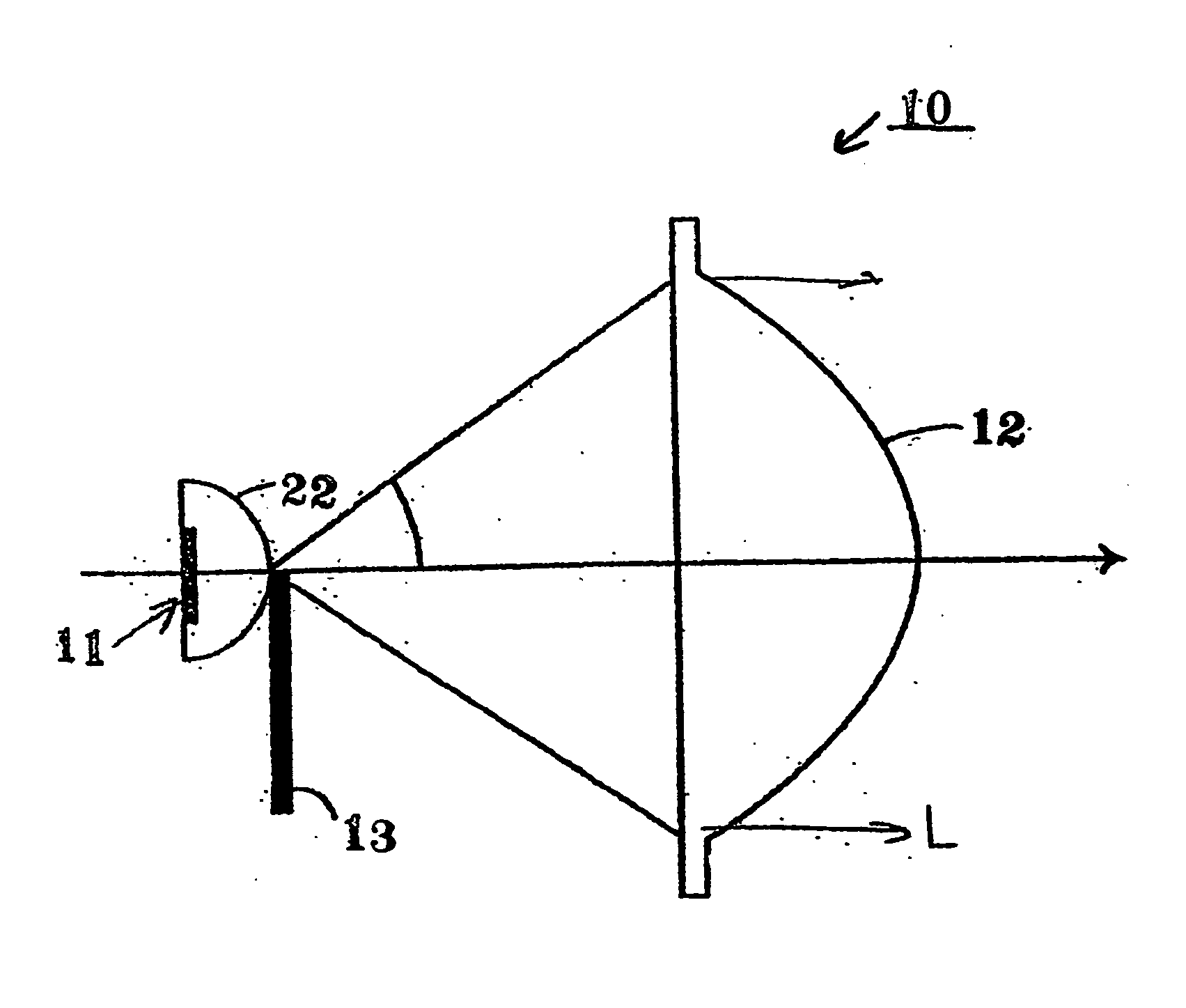
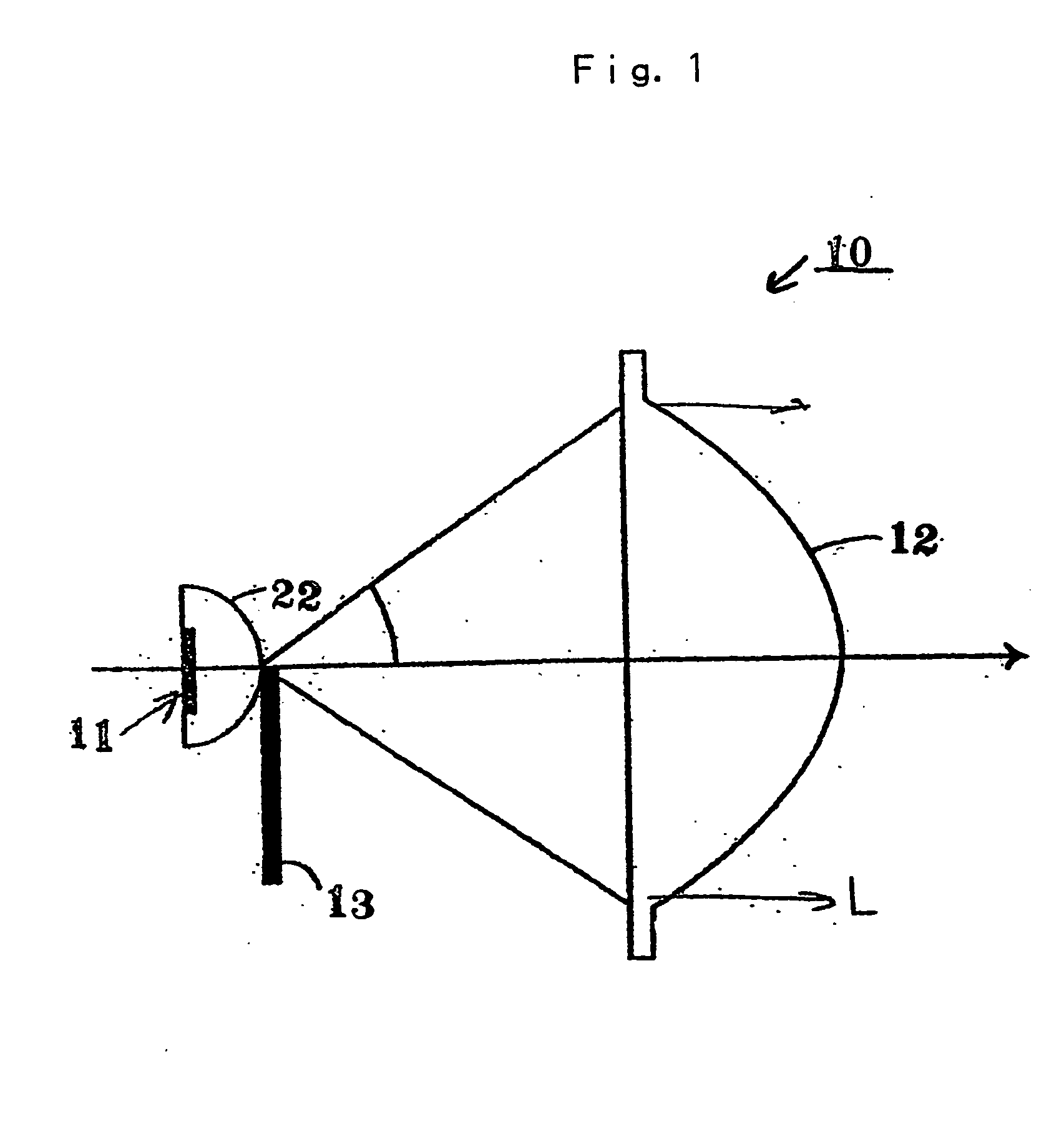
[0051]FIG. 1 illustrates a configuration of a vehicle lamp and light source apparatus made in accordance with the principles of the present invention.

[0052] In FIG. 1, a vehicle lamp 10 can include a light source apparatus 11, a projection lens 12 for converging light from the light source apparatus 11, and a light shielding plate 13 located in the optical path between the light source apparatus 11 and the projection lens 12. The light shielding plate 13 can be configured to form a given light distribution shape and characteristic to the light emitted from the vehicle lamp 10.

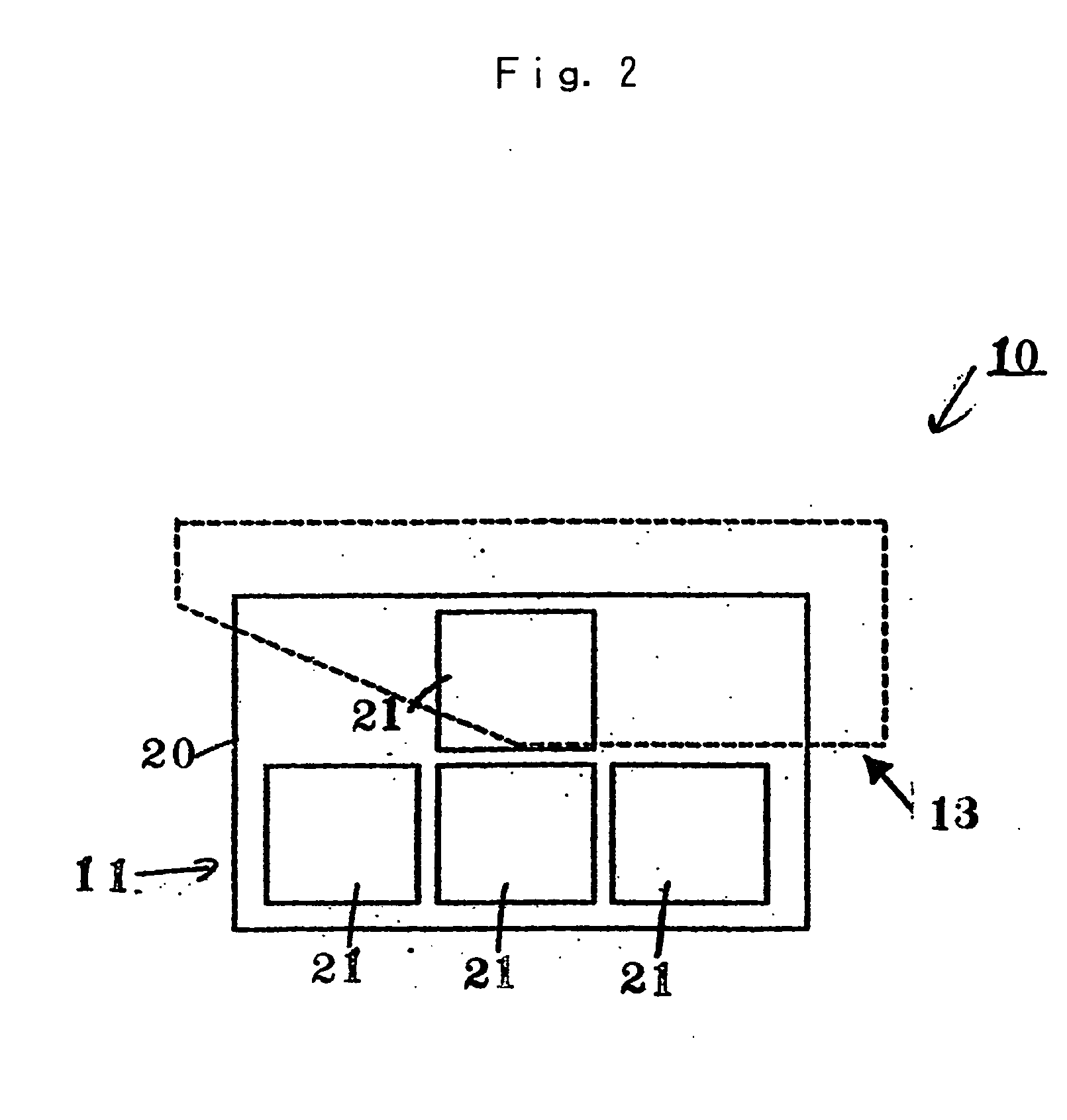
[0053] The light source apparatus 11 can include a plur...


PUM


Abstract

A light source apparatus for vehicle lamps and particularly vehicle headlights can include a plurality of LED elements mounted in a cavity located on a base surface or on a base. Each of the LED elements can be arranged in such a manner as to form an emission shape and a brightness distribution that is suited for a light distribution pattern, and especially a light distribution pattern for vehicle headlight.

Description

[0001] This invention claims the benefit of Japanese patent application No. 2003-208077, filed on Aug. 20, 2003, which is hereby incorporated by reference. FIELD OF THE INVENTION [0002] The present invention relates to a light source and more particularly a light source for a vehicle lamp or headlight. The light source can employ a plurality of LED elements and can be configured as a vehicle lamp, such as a headlight or an auxiliary headlight. DESCRIPTION OF THE RELATED ART [0003] Today, discharge lamps such as halogen lamps or HIDs are used as light sources for headlights, auxiliary headlights and other vehicle lamps. [0004] However, a white LED light source is drawing attention as a possible substitute for the existing light sources, and its application to vehicle lamps for illumination purposes is becoming more realistic as a result of recent achievements in increasing the efficiency and manufacturability of high output and high brightness LED light sources. [0005] The white LED ...

Claims


Application Information

Patent Timeline
IPC IPC(8): F21S8/10F21S8/12F21V11/00F21V11/16F21Y101/00H01L25/075H01L33/00
CPCF21S48/1154F21S48/1159F21S48/145F21S48/1747F21Y2101/02F21Y2105/003H01L2924/0002H01L25/0753H01L33/20H01L2924/00F21Y2105/10F21Y2105/12F21Y2115/10F21S41/143F21S41/151F21S41/18F21S41/43F21S41/663
Inventor YATSUDA, YASUSHIKOIKE, TERUOKUSHIMOTO, TAKUYA
Owner STANLEY ELECTRIC CO LTD
Why Eureka
Try Eureka