Liquid crystal display device

Active Publication Date: 2011-01-13
LG DISPLAY CO LTD
View PDF14 Cites 15 Cited by
  • Summary
  • Abstract
  • Description
  • Claims
  • Application Information

AI Technical Summary

Benefits of technology

[0036]As described above the LCD according to an exemplary embodiment of the present invention can properly cope with an environmental regulation that is gradually strengthened, because it does not cause such a problem with the environmental regulation as a CCFL.
[0037]In addition, because the LED PCB with the reflection layer formed on surface thereof is installed at an upper side of the LED array and the reflection plate extends such that it sufficiently covers the lower portion of the LED array to thus make light emitted from the light source incident to its maximum level, thus making the LCD device thinner, and accordingly, coping with the r

Problems solved by technology

However, the backlight using the CCFL has not good color reproduction because the light source, namely, the CCLF, does not have good light emission characteristics.
In addition, the size and capacity of the fluorescent lamp are limited, a backlight of a high luminance cannot be obtained.
In addition, because mercury applied as phosphor to the CCFL is harmful to a human body, it cannot cope with the environment regulation which is gradually strengthened.
However, the performances such as the min

Method used


Image

  • Liquid crystal display device
  • Liquid crystal display device
  • Liquid crystal display device

Examples


Example

[0044]A liquid crystal display (LCD) device according to an exemplary embodiment of the present invention will now be described in detail with reference to the accompanying drawings.

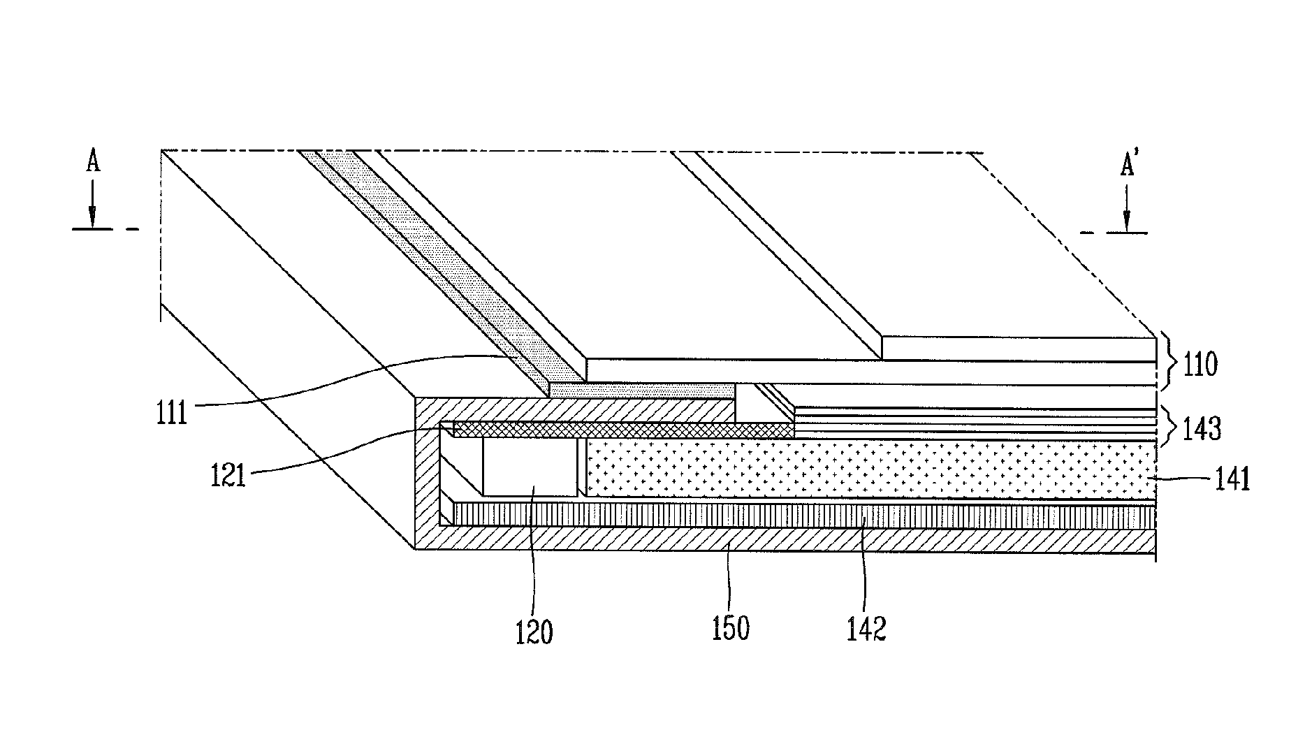
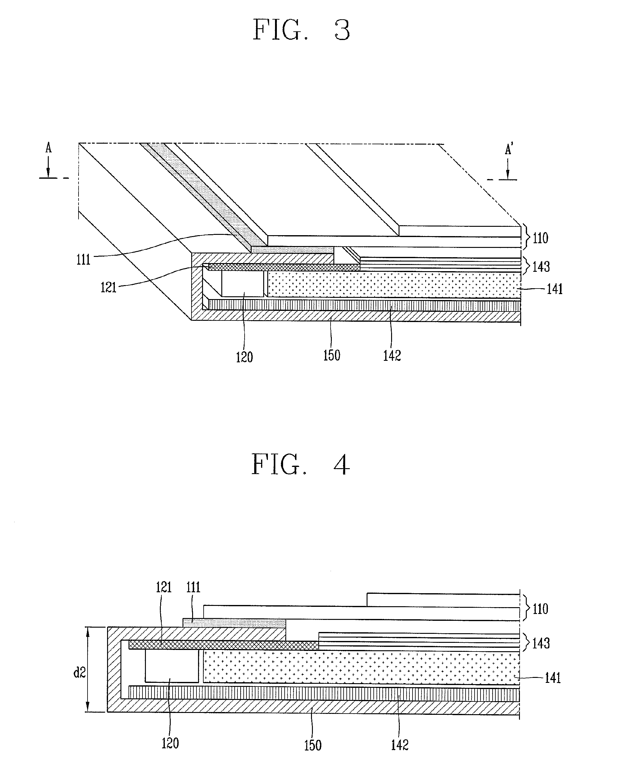
[0045]FIG. 3 is a perspective view schematically showing the structure of an LCD using LED emission lamps according to an exemplary embodiment of the present invention, and FIG. 4 is a sectional view taken along line A-A′ of the LCD illustrated in FIG. 3.

[0046]As illustrated, in the LCD device according to an exemplary embodiment of the present invention, an LED array 120 for generating light and a reflection plate 142 are installed on a lower cover 150, and an LED PCB 121 on which a certain driving circuit for driving the LED is mounted is attached to an upper portion of the lower cover 150 above the LED array 120.

[0047]A light guide plate 141 is installed in a direction in which the LED array 120 outputs light, and a plurality of LEDs (not shown) constituting the LED array 120 may be positioned at a ce...


PUM


Abstract

In a liquid crystal display (LCD) device, an LED PCB with the reflection layer formed on surface thereof is installed at an upper side of the LED array and a reflection plate extends such that it sufficiently covers the lower portion of the LED array to thus make light emitted from the light source incident to its maximum level, thus coping with the reduction in the quantity of light resulting from making the LCD device thinner. The LCD device includes: a liquid crystal panel; an LED array supplying light to the liquid crystal panel; a light guide plate installed in a direction in which the LED outputs light, and guiding light; a reflection plate formed between the LED array and a lower portion of a lower cover; and an LED PCB attached to an upper portion of the lower cover at an upper side of the LED array and having a reflection layer formed at a side facing the light guide plate. Because an existing LED housing reflector is removed, a cost and processing time can be reduced and an assembling process is simplified to improve a defective rate and production yield.

Description

BACKGROUND OF THE INVENTION[0001]1. Field of the Invention[0002]The present invention relates to a liquid crystal display (LCD) device and, more particularly, an LCD device for supplying light to a liquid crystal panel by using a plurality of light emitting diodes (LEDs).[0003]2. Description of the Related Art[0004]In general, an LCD is a display device for displaying a desired image by adjusting a light transmittance of pixels by separately supplying data signals according to image information to the pixels arranged in a matrix form.[0005]Accordingly, the LCD device includes a driving unit for driving the liquid crystal display panel with the pixels arranged in the matrix form thereon and the pixels.[0006]The liquid crystal panel includes a thin film transistor (TFT) array substrate and a color filter substrate attached in a facing manner with a uniform cell gap maintained therebetween, and a liquid crystal layer formed in the cell gap between the array substrate and the color filt...

Claims


Application Information

Patent Timeline
IPC IPC(8): G02F1/1335G02F1/13
CPCG02F1/133608G02F1/133615G02F2001/133612G02F1/133603G02F1/133524G02B6/0011G02B6/0088G02B6/0028G02B6/0073G02F1/133612G02F1/1335
Inventor LEE, SANG-HYUNMOON, WON-TAEKHWANG, YONG-IK
Owner LG DISPLAY CO LTD
Why Eureka
Try Eureka