Lens barrel

Inactive Publication Date: 2006-03-28
ASAHI KOGAKU KOGYO KK
View PDF14 Cites 8 Cited by
  • Summary
  • Abstract
  • Description
  • Claims
  • Application Information

AI Technical Summary

Benefits of technology

[0008]The present invention provides a lens barrel having a simple structure, which minimizes reduction in light quantity of marginal rays.

Problems solved by technology

Such conventional compact zoom cameras have a problem where the illumination of the marginal area of an image is smaller than that of the center of the image due to the optical properties of the lens.
Specifically, in compact cameras the vignetting factor tends to be small (approximately 50 percent, image height≈0.9Y) due to the lens design, thus resulting in a lack of light quantity of marginal rays even if the diaphragm is set to a small aperture.
However, such a shutter unit is complicated in structure and difficult to be controlled, which may cause deterioration in precision of the aperture size to thereby lose half the initial effect of adopting the diaphragm shutter.
However, such a modification inevitably increases the size of the compact zoom camera.

Method used


Image

  • Lens barrel
  • Lens barrel
  • Lens barrel

Examples


first embodiment

[First Embodiment]

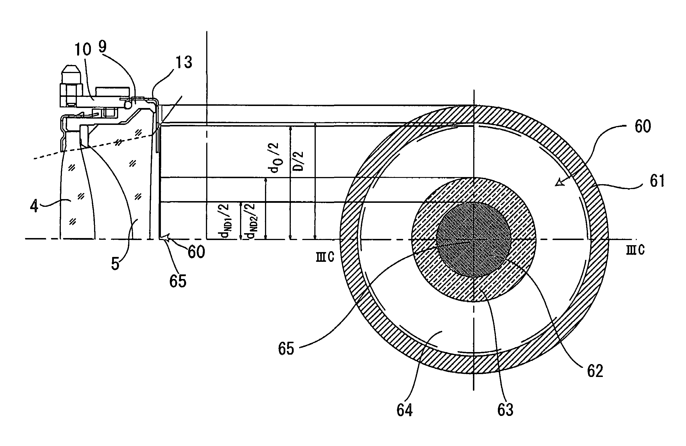
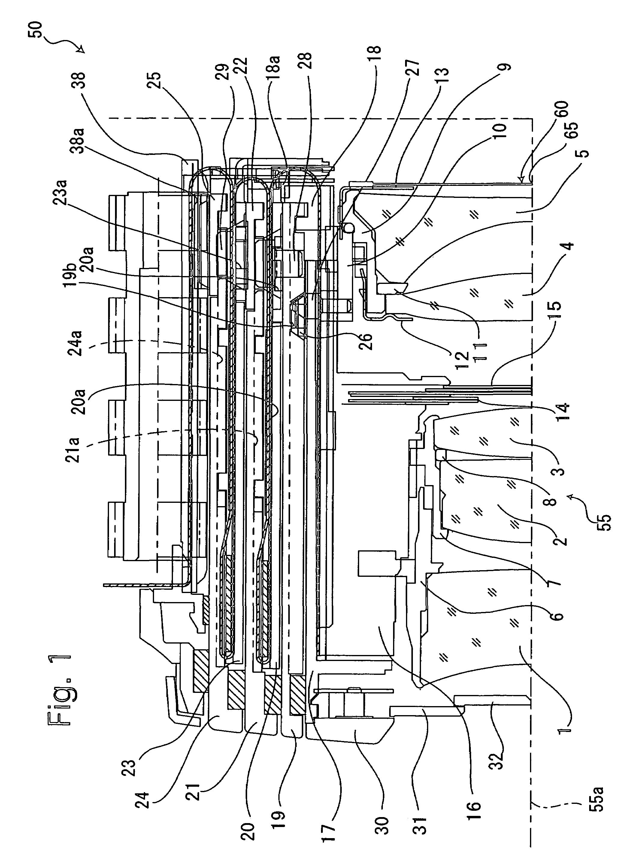
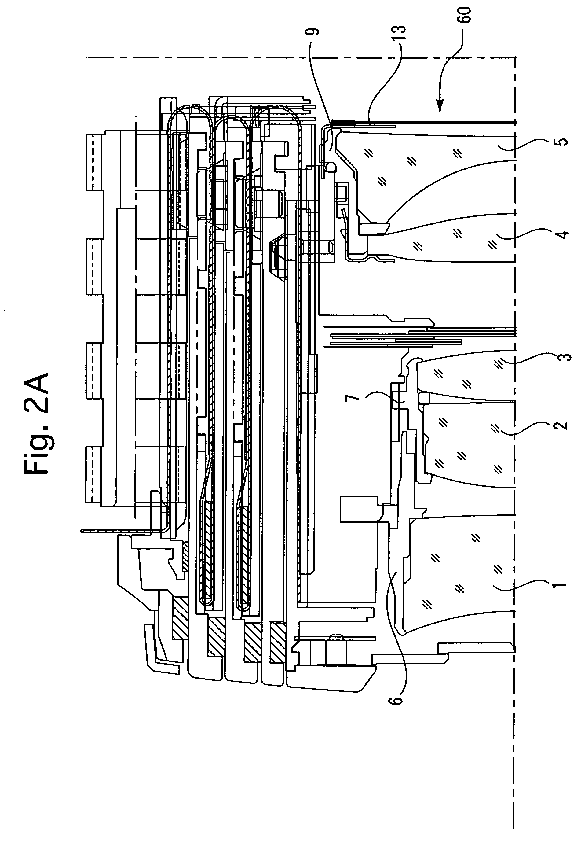
[0063]FIGS. 1 through 2C show a first embodiment of a lens barrel according to the present invention. As can be appreciated from FIGS. 1 through 2C, the lens barrel 50 is a telescoping type zoom lens of a camera which is provided with four external telescoping barrels: a first external barrel (lens support barrel) 17, a second external barrel (cam ring) 19, a third external barrel 21 and a fourth external barrel 24 which are concentrically arranged about an optical axis 55a of a photographing optical system 55 of the lens barrel 50. The photographing optical system 55 of the lens barrel 50 includes a first lens group (lens element) 1, a second lens group (lens element) 2, a third lens group (lens element) 3, a diaphragm (diaphragm blades) 14, a shutter (shutter blades) 15, a fourth lens group (lens element) 4, and a fifth lens group (lens element) 5, in that order from the object side (the left side as viewed in FIG. 1). The lens barrel 50 is provided around the fo...

second embodiment

[Second Embodiment]

[0088]FIGS. 13 through 14C show a second embodiment of the lens barrel according to the present invention. Similar to the first embodiment of the lens barrel shown in FIG. 13, the lens barrel 150 is a telescoping type zoom lens of a camera which is provided with four external telescoping barrels: a first external barrel (lens support barrel) 117, a second external barrel (cam ring) 119, a third external barrel 121 and a fourth external barrel 124, which are concentrically arranged about an optical axis 155a of a photographing optical system 155 of the lens barrel 150. The photographing optical system 155 of the lens barrel 150 includes a first lens group (lens element) 101, a second lens group (lens element) 102, a third lens group (lens element) 103, a diaphragm (diaphragm blades) 114, a shutter (shutter blades) 115, a fourth lens group (lens element) 104, a fifth lens group (lens element) 105, in that order from the object side (the left side as viewed in FIG. 1...


PUM


Abstract

A lens barrel includes an optical system including a short focal length for a wide angle of view; and an ND filter in the shape of a disc which is provided on an optical axis of the optical system. An optical density of the ND filter decreases in a direction radially outwards from a center of the ND filter.

Description

BACKGROUND OF THE INVENTION[0001]1. Field of the Invention[0002]The present invention relates to a lens barrel which includes a short focal length for a wide angle of view.[0003]2. Description of the Related Art[0004]Compact zoom cameras having a zoom lens whose focal length at the wide-angle extremity is approximately 28 mm, 35 mm or 38 mm have been popularized in recent years.[0005]Such conventional compact zoom cameras have a problem where the illumination of the marginal area of an image is smaller than that of the center of the image due to the optical properties of the lens. Specifically, in compact cameras the vignetting factor tends to be small (approximately 50 percent, image height≈0.9Y) due to the lens design, thus resulting in a lack of light quantity of marginal rays even if the diaphragm is set to a small aperture.[0006]To combat this problem, a compact zoom camera in which an iris diaphragm is incorporated in a shutter unit has been produced. However, such a shutter u...

Claims


Application Information

Patent Timeline
IPC IPC(8): G02B15/14G02B26/02G02B5/22G03B21/14H04N5/238G02B5/20G02B7/10
CPCG02B7/102G02B5/205
Inventor SATO, NORIOSUZUKI, TOSHIHARU
Owner ASAHI KOGAKU KOGYO KK
Why Eureka
Try Eureka