Switching electric source device

a technology of switching electric source and output voltage, which is applied in the direction of dc-dc conversion, climate sustainability, power conversion systems, etc., can solve the problems of deteriorating detection accuracy of detection circuit with respect to output voltag

Active Publication Date: 2005-02-24
MURATA MFG CO LTD
View PDF5 Cites 27 Cited by
  • Summary
  • Abstract
  • Description
  • Claims
  • Application Information

AI Technical Summary

Benefits of technology

[0021] In order to solve the above-described problems, preferred embodiments of the present invention provide a switching electric source device including a transformer, a main switching element connected to a primary winding of the transformer, a secondary rectifying smoothing circuit for rectifying and smoothing electric power output from a secondary winding of the transformer based on the switch on-off operation of the main switching element, and externally outputting the rectified, smoothed electric power, a detection circuit for indirectly detecting the output voltage from the secondary rectifying smoothing circuit utilizing voltage induced in a third winding of the transformer, and a control circuit for controlling the switch on-off operation of the main switching element for stabilization of the output voltage from the secondary rectifying smoothing circuit based on the detection voltage for the output voltage obtained by the detection circuit, wherein the secondary rectifying smoothing circuit includes a first synchronous rectifier connected in series with the secondary winding and performing the same switch on-off operation as that of the main switching element, and a second synchronous rectifier connected in parallel to the secondary winding and performing the switch on-off operation inverting that of the main switching element, the first and second rectifiers being operative to rectify the output power from the secondary winding, and a first synchronous rectifier control circuit is provided, which detects the resonance state generated based on the exciting energy of the primary winding after the main switching element switches off, and causes the first synchronous rectifier to switch on earlier during the time period from the completion of the resonance state to the switching on of the main switching element, based on the detection signal for the resonance state.
[0022] According to the above-described preferred embodiment of the present invention, the first synchronous rectifier control circuit is provided, which causes the first synchronous rectifier to switch on earlier during the time period (the time period A) ranging from the completion of the resonance state on the primary side to the switching on of the main switching element in the OFF time period of the main switching element. Thus, the first synchronous rectifier can be switched on during the time period A by the first synchronous rectifier control circuit. This switch-on operation of the first synchronous rectifier causes the exciting current of the secondary winding to flow between the drain-source of the first synchronous rectifier (MOSFET). Thus, current can be prevented from flowing through the body diode (parasitic diode) of the first synchronous rectifier. Accordingly, a problem in that the detection accuracy of the detection circuit with respect to the output voltage is deteriorated during the time period A can be solved. The above-described deterioration of the detection accuracy is caused by the induced voltage of the third winding which is developed due to the voltage drop in the body diode of the first synchronous rectifier during the time period A. Accordingly, a predetermined output voltage can be stably output from the secondary rectifying smoothing circuit, irrespective of the variation of the input voltage and that of the ambient or environmental temperature. Thus, the reliability of the switching electric source device can be considerably enhanced. Also, in the case where an external diode is provided for the first synchronous rectifier, the same advantages as described above can be obtained.
[0024] Preferably, a circuit including a resistor and a rectifying element connected in parallel is connected to a power conduction line between the circuit including the DC cut capacitor and the rectifying element connected in series and the switching control terminal of the first synchronous rectifier. Thereby, the resistor of the circuit including the resistor and the rectifying element connected in parallel, and the internal capacitance (parasitic capacitance) of the first synchronous rectifier can constitute a time constant circuit. Thus, the timing at which the first synchronous rectifier switches on during the time period A can be easily controlled by adjustment of the time constant of the time constant circuit. Moreover, when the first synchronous rectifier is caused to switch off, the voltage of the switching control terminal of the first synchronous rectifier can be steeply increased, due to the forward characteristic of the rectifying element of the circuit including the resistor and the rectifying element.
[0025] Preferably, the first synchronous rectifier control circuit includes an off-control circuit which causes the electric charges stored between the gate-source of the first synchronous rectifier to be discharged and thus, causes the first synchronous rectifier to switch off, when the main switching element switches off. Accordingly, when the main switching element switches off, the electric charges stored between the gate-source of the first synchronous rectifier can be instantaneously discharged, and the gate-source voltage of the first synchronous rectifier can be reduced to the 0 level. Thereby, disturbance of the circuit operation of the switching electric source device can be eliminated. For example, the above-described disturbance occurs due to reversed current or the like which is due to the electric charges remaining between the gate-source of the first synchronous rectifier immediately after the main switching element switches off.

Problems solved by technology

Accordingly, a problem in that the detection accuracy of the detection circuit with respect to the output voltage is deteriorated during the time period A can be solved.

Method used


Image

  • Switching electric source device
  • Switching electric source device
  • Switching electric source device

Examples


Embodiment Construction

[0040] Hereinafter, preferred embodiments according to the present invention will be described with reference to the drawings.

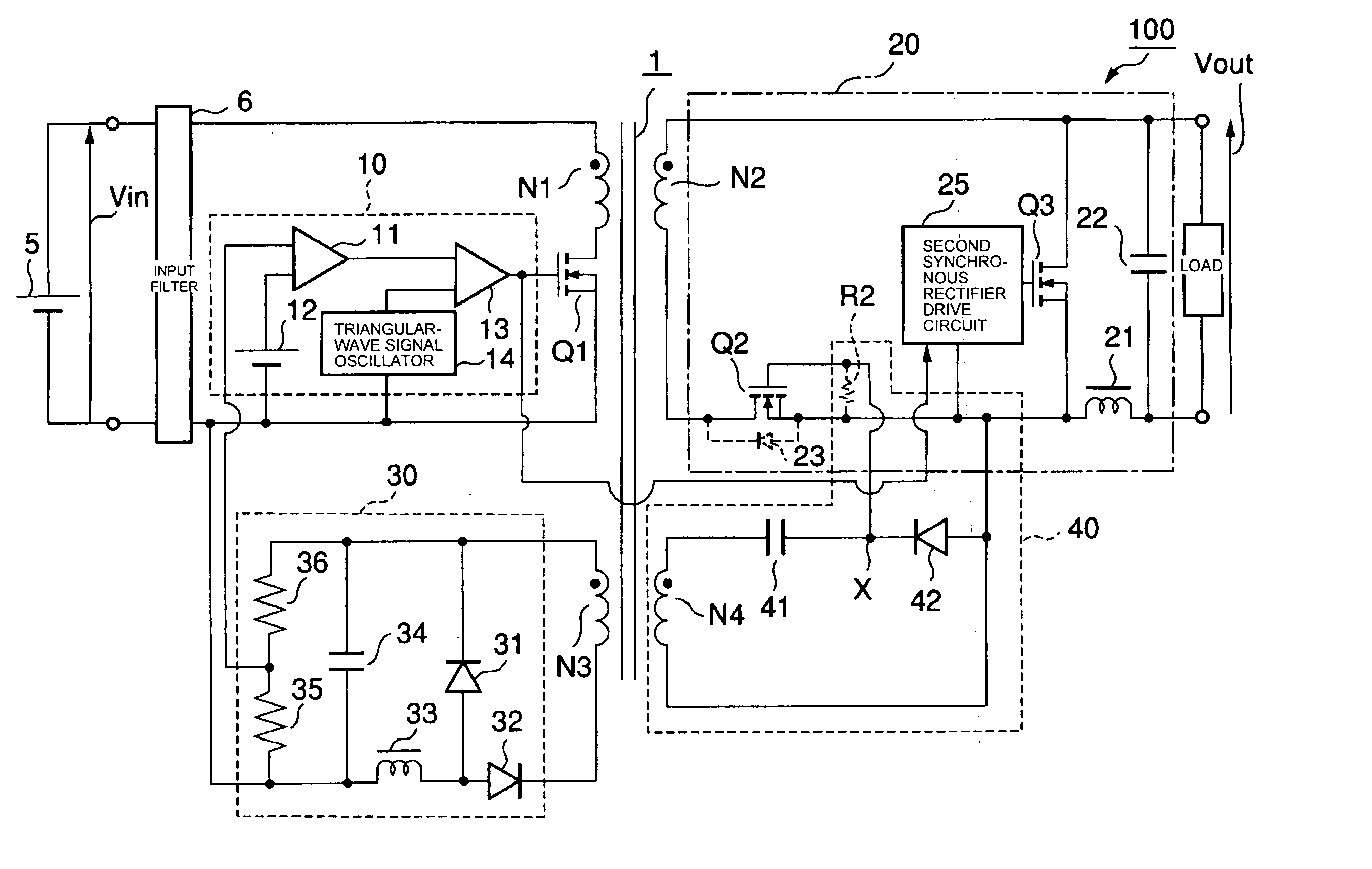
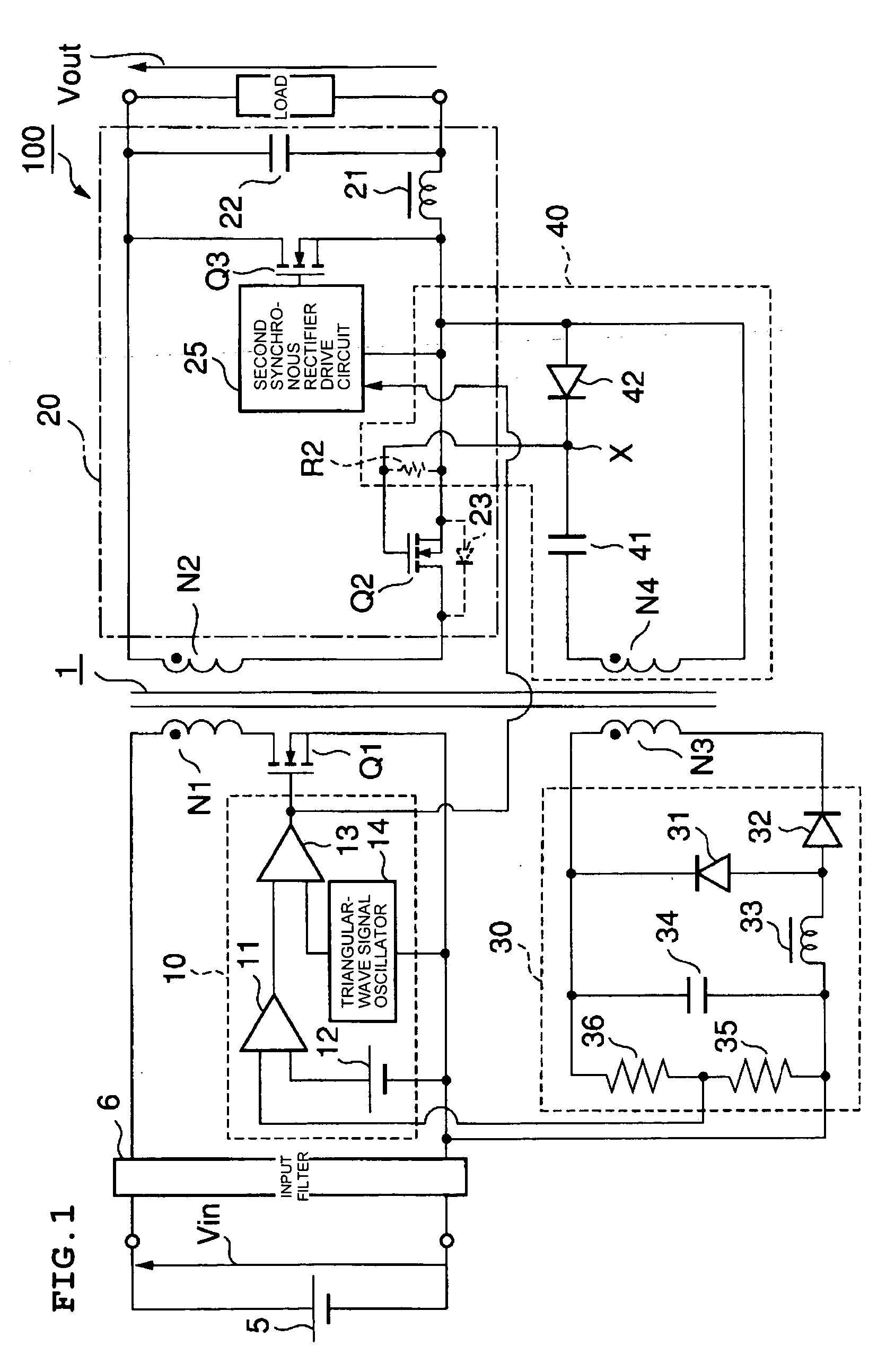
[0041]FIG. 1 shows the main circuit components of a switching electric source device according to a first preferred embodiment of the present invention. In the description of the first preferred embodiment, the same components as those of the switching electric source device 200 shown in FIG. 9 are designated by the same reference numerals, and the description thereof is not repeated.

[0042] The switching electric source device 100 according to the first preferred embodiment includes of a forward-type DC-DC converter. In the switching electric source device 100, a transformer 1 is provided with a fourth winding N4 in addition to a primary winding N1, a secondary winding N2, and a third winding N3.

[0043] A circuit including a DC-cut capacitor 41 and a diode 42 as a rectifying element connected in series is connected in series with the fourth winding N4 with ...


PUM


Abstract

A switching electric source device includes a first synchronous rectifier control circuit, which detects the resonance state developed based on the exciting energy of the primary winding after the main switching element switches off, and causes a first synchronous rectifier to switch on earlier during the time period from the completion of the resonance state to the switching on of the main switching element. Thus, the first synchronous rectifier switches on during the time period, and thus, current is prevented from flowing through a body diode, so that a voltage caused by the voltage drop in the body diode is prevented from being induced in the secondary winding and the third winding. As a result, variations in the output voltage, which is caused by the induced voltage of the third winding, can be prevented. The output voltage can be stabilized.

Description

BACKGROUND OF THE INVENTION [0001] 1. Field of the Invention [0002] The present invention relates to a switching electric source device including a transformer and a circuit for rectifying electric power output from a secondary winding of the transformer by use of a synchronous rectifier. [0003] 2. Description of the Related Art [0004] A switching electric source device has been proposed which is provided with a detection circuit for indirectly detecting an output voltage, and controls a main switching element based on detection results by the detection circuit according to a PWM system (e.g., see Japanese Unexamined Patent Application Publication No. 2001-25245 (Patent Document 1)). FIG. 9 shows an example of a circuit configuration of major components of the switching electric source device having the detection circuit described above. [0005] The switching electric source device 200 contains a transformer 1. A main switching element (MOSFET) Q1 is connected to the primary winding ...

Claims


Application Information

Patent Timeline
Patent Type & Authority Applications(United States)
IPC IPC(8): H02M3/335H02M3/28
CPCY02B70/1475H02M3/33592Y02B70/10H02M3/28
Inventor NAGAI, JUNTSUJI, HITOSHI
Owner MURATA MFG CO LTD
Why Eureka
Try Eureka