

Mixing in microfluidic devices
a microfluidic device and mixing technology, applied in the field of microfluidic devices, can solve the problems of mixing samples, difficult mixing of samples with conditioning liquids, and the need for expensive devices, including active elements, to achieve the effect of easy mixing and mixing, and high efficiency
- Summary
- Abstract
- Description
- Claims
- Application Information
AI Technical Summary
Benefits of technology
Problems solved by technology
Method used
Image

Examples
example 1
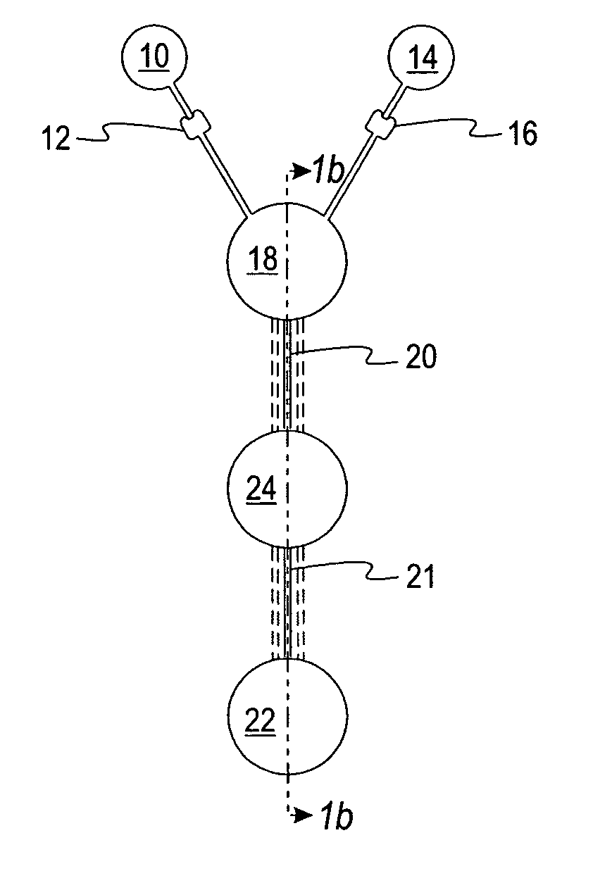
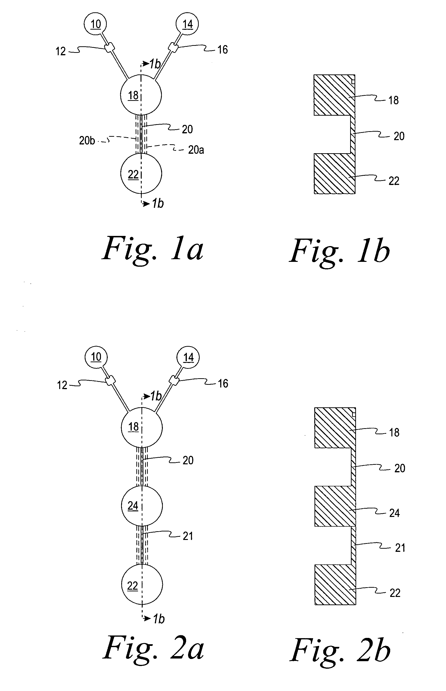
[0060] A microfluidic device was made having the general configuration shown in FIG. 1, including five parallel capillaries 20 et al connecting chambers 18 and 22.
[0061] The sample well 10 was filled with 10 μL of a phenol red solution with buffer (pH 4.0). The well 14 was filled with 10 μL of a solution of phenol red (pH 7.0). 10 mm long capillaries connected the sample and reagent chambers to the first chamber 18. Each capillary was 200 μm deep and 700 μm wide, containing 0.4 μL. The first chamber 18 was 5.5 mm in diameter, 1.5 mm deep, and had a capacity of about 36 μL. The second chamber 22 was 5.5 mm in diameter and 1.1 mm deep, with a capacity of about 26 μL. The device was placed on a platform and rotated at 2500 rpm at a distance of about 28 mm to overcome the resistance of the stops 12 and 16 and to deliver the liquids from wells 10 and 14 at the same time to first chamber 18. The mixed liquids passed immediately through five capillary passageways (20 et al) connecting fir...
example 2
[0063] Another microfluidic device was made, which differed from the device of Example 1 in that only one capillary passageway connected the first chamber 18 and the second chamber 22. Also, the second chamber 22 was provided with a series of five steps ramped down in the direction of the centrifugal force that was applied. The first chamber 18 was 5.5 mm in diameter, 1.5 mm deep, and had a capacity of about 36 μL. The second chamber 22 was 5 mm wide and 7 mm long with an average depth of about 1.2 mm and a volume of about 46 μL. The single capillary (3 mm long, 200 μm deep, 500 μm wide) exited at the top of the stepped ramp. The mixing chamber and the two capillaries supplying the dilution chamber had the same dimensions as in Example 1.
[0064] 10 μL of a phenol red solution (pH. 7.0) was added to well 10 and 10 μL of phenol red solution with buffer (pH 4.0) was added to well 14. The device was rotated at a speed which was sufficient to overcome the capillary stops and deliver the ...
example 3
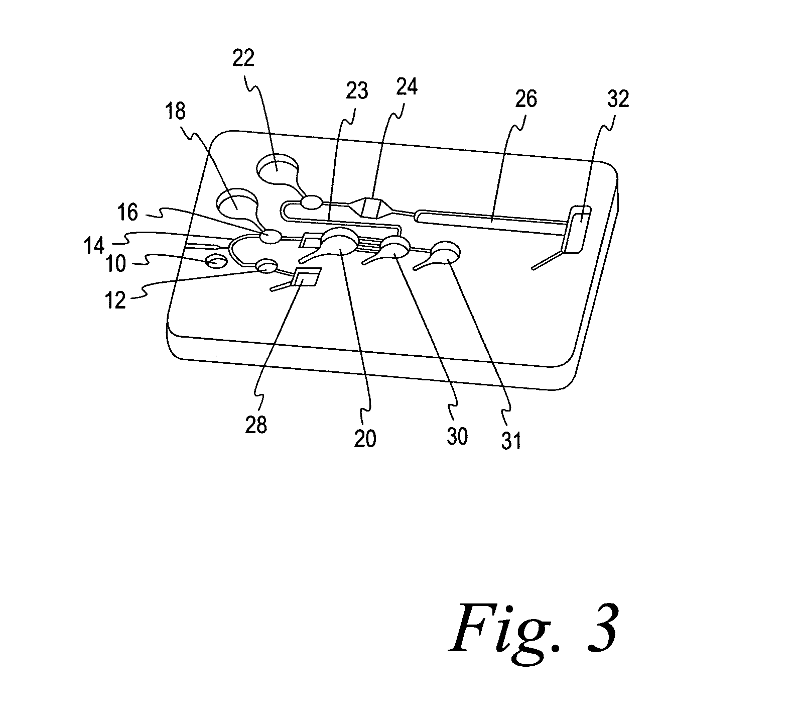
[0065] In this example, a test for HbA1c was carried out in a microfluidic chip of the type shown in FIG. 3. The surface energy of the internal features had been adjusted to provide a contact angle of 25° for water on the surface and were covered with a polypropylene film lid (Excel 2930). A sample of blood was introduced via sample port 10, from which it proceeded by capillary action to the pre-chamber 12 and then to metering capillary 14. The auxiliary metering well 16 is optional, only being provided where the sample size requires additional volume. The volume of the sample in capillary 14 and well 16 was 0.3 μL. The denaturant / oxidizing liquid (9.62 μL) (Sigma mammalian cell lysis / extraction reagent) was contained in well 18. It was emptied into the first chamber 20 (18.84 μL) at the same time the metering well 16 and the associated metering capillary 14 are emptied by application of centrifugal force by spinning at 1200 rpm at a distance of 29 mm to overcome the capillary stops...
PUM
| Property | Measurement | Unit |
|---|---|---|
| length | aaaaa | aaaaa |
| length | aaaaa | aaaaa |
| velocity | aaaaa | aaaaa |
Abstract
Description
Claims
Application Information