Perpendicular magnetic recording media

a magnetic recording medium and perpendicular magnetic technology, applied in the field of magnetic recording medium and magnetic storage apparatus, can solve the problem of difficult to achieve the density of areal recording more than 50 gb/insup>2

Inactive Publication Date: 2005-02-24
HITACHI GLOBAL STORAGE TECH JAPAN LTD
View PDF11 Cites 8 Cited by
  • Summary
  • Abstract
  • Description
  • Claims
  • Application Information

AI Technical Summary

Benefits of technology

[0005] The inventors of the invention have found that the prior art method in which the magnetization of the soft magnetic underlayer is directed in one direction by the hard magnetic pinning layer is apt to cause magnetic domains of the reverse direction at the inner and outer edges of a disk substrate with result that the spike noise occurring from these portions is observed. The inventors of the invention have further found that, although the other prior art method in. which the domain wall motion of the soft magnetic underlayer is suppressed by the antiferromagnetic layer is effective in suppressing the disappearance of the recorded magnetization caused by the domain wall motion, it is impossible to suppress the spike noise caused by the domain walls.
[0006] The invention is made to solve the above problem occurring in the prior arts. More specifically, the object of the invention is to provide a perpendicular magnetic recording medium having a recording density not less than 50 Gb / in2 and a high S / N ratio regarding the medium while suppressing the spike noise by controlling the magnetic domains of the soft magnetic underlayer, and to thereby make it easy to realize a magnetic storage apparatus of a high recording density.

Problems solved by technology

However, as the areal recording density is raised, a problem of so-called thermal fluctuation comes to be caused in which magnetically recorded data disappear due to surrounding heat, so that the achieving of an areal recording density more than 50 Gb / in2 is considered to be difficult insofar as a conventional longitudinal recording method is concerned.
However, since the double-layer perpendicular recording medium has the soft magnetic underlayer having a high saturation magnetic flux density (Bs), there occur such problems as a stray field occurring from the domain walls of the soft magnetic underlayer is observed as spike noises and-as the recorded magnetization disappears due to the domain wall motion.

Method used


Image

  • Perpendicular magnetic recording media
  • Perpendicular magnetic recording media
  • Perpendicular magnetic recording media

Examples


embodiment 1

[0037] Embodiment 1

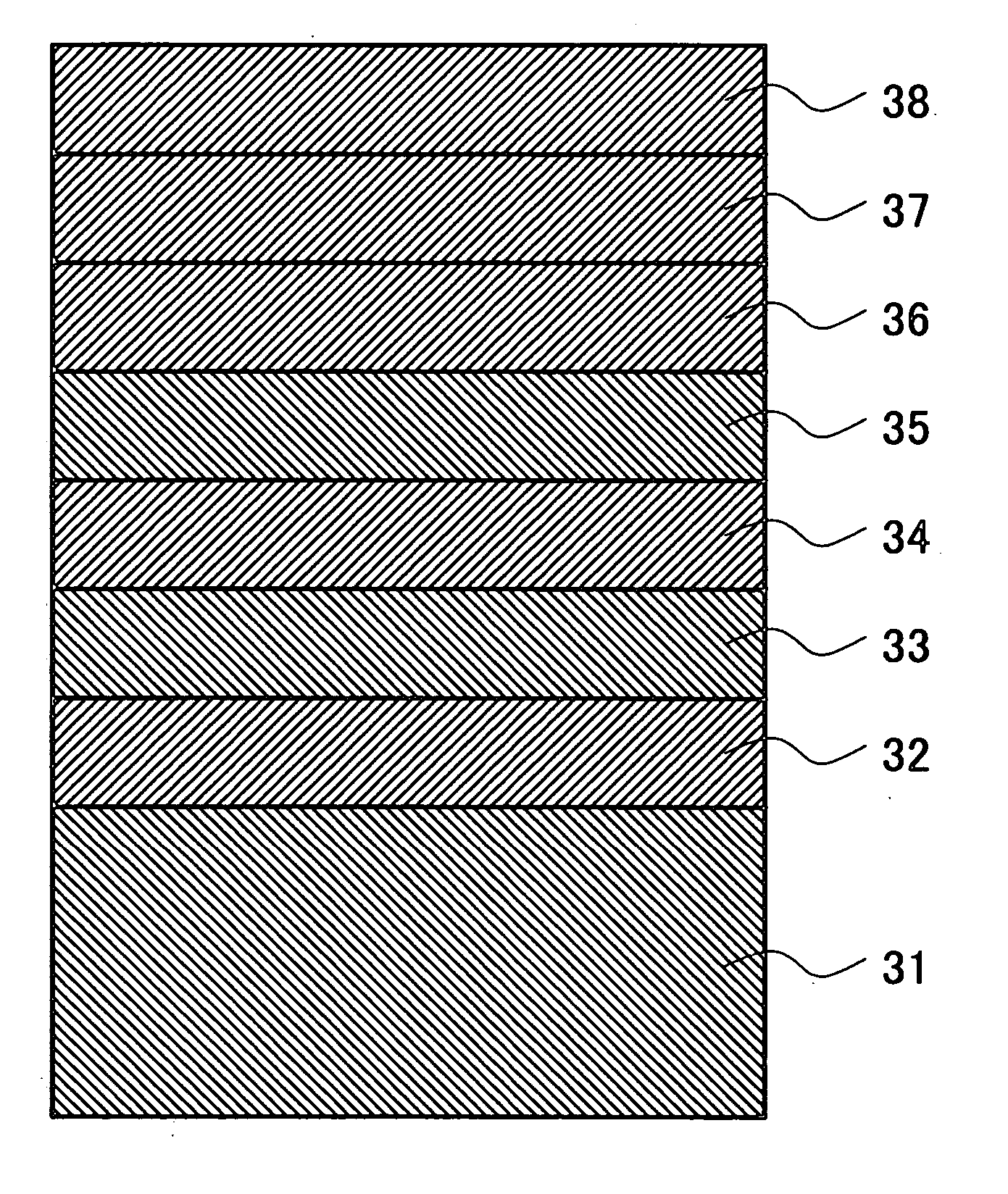
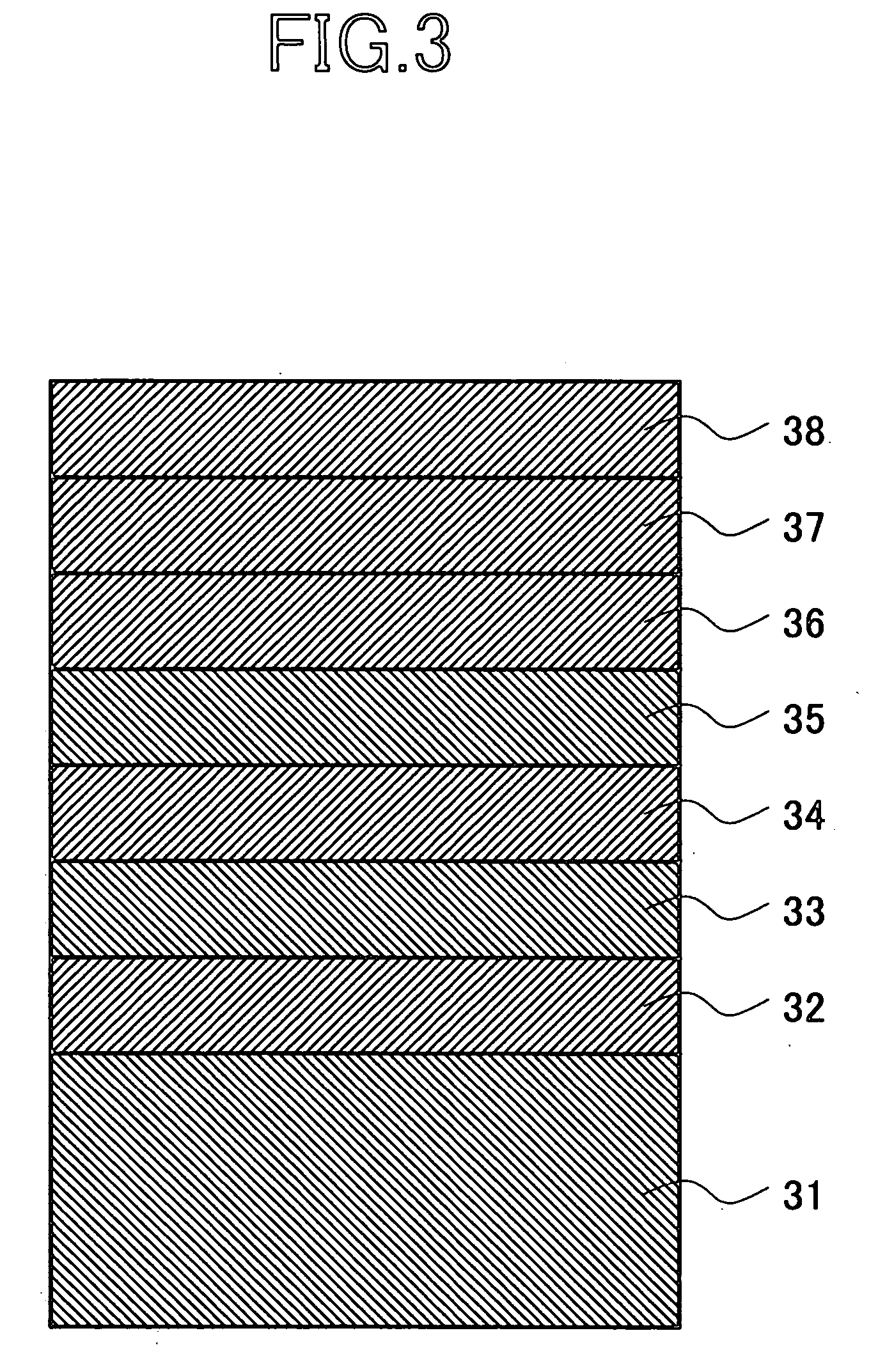
[0038] A perpendicular magnetic recording medium according to the first embodiment of the invention comprises a substrate, a domain-control layer provided on the substrate, a soft magnetic underlayer, and a perpendicular recording layer, all of which are laminated in succession in this order. As the domain-control layer, there is used a bi-layer film comprising a non-magnetic layer of fcc structure and a antiferro-magnetic layer, or a tri-layer film comprising a non-magnetic layer of fcc structure, a antiferromagnetic layer and a crystalline ferromagnetic layer. In addition, the medium is subjected to a heat treatment in a magnetic field.

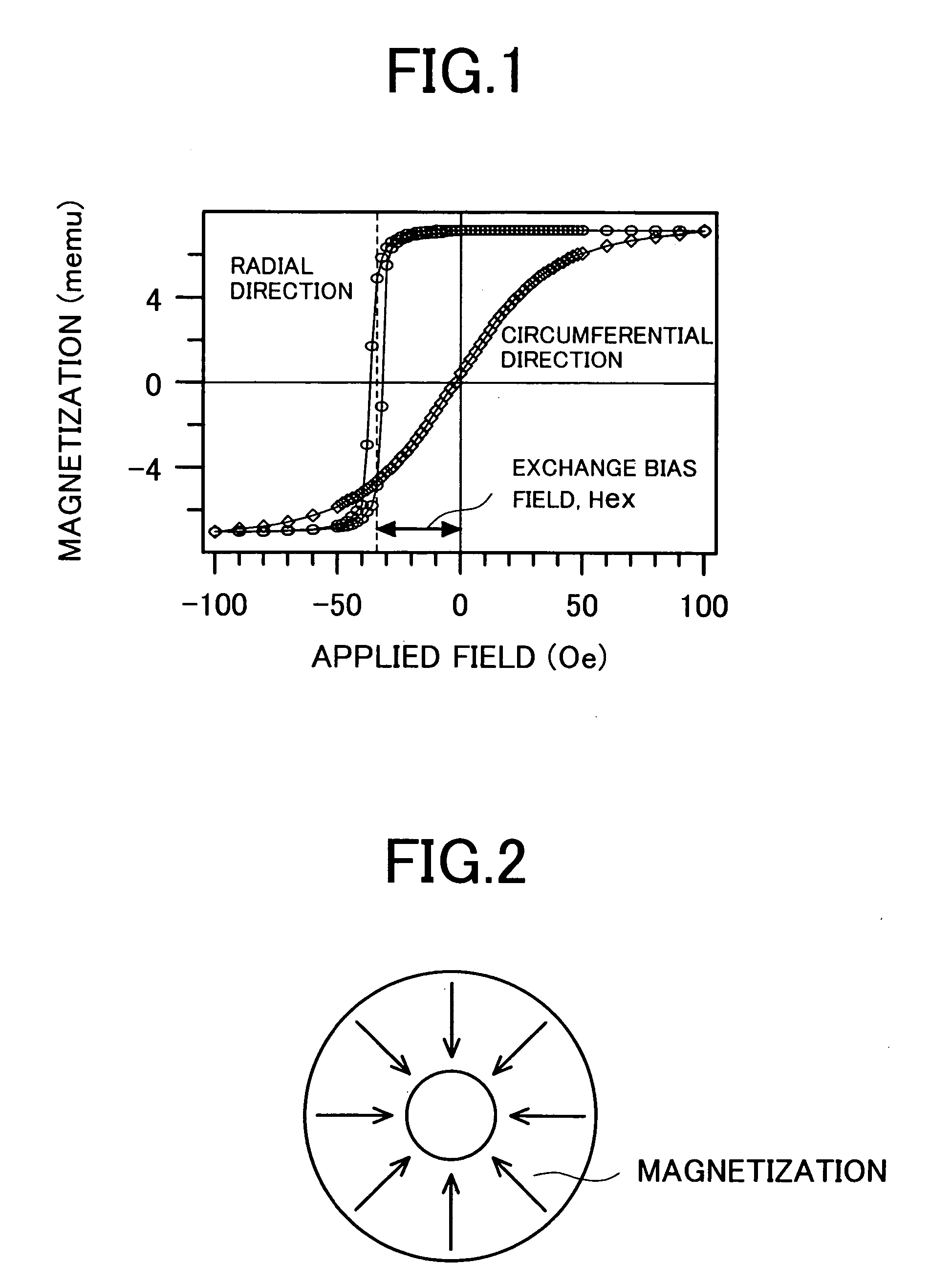
[0039] The heat treatment in the magnetic field for controlling the domain structure of the soft magnetic underlayer is performed by the steps of performing, after forming the perpendicular recording layer, a heating at about a blocking temperature while applying a magnetic field in the radial direction of the disk substrate, and...

embodiment 2

[0046] Embodiment 2

[0047] By using a layered structure similar to that of the perpendicular magnetic recording medium of Embodiment 1 and by using, as a domain-control layer 33, a tri-layer film constituted by a non-magnetic layer 81, an antiferromagnetic layer 82 and the crystalline ferromagnetic layer 83 as shown in FIG. 8, there was produced a perpendicular magnetic recording medium. In Table 2 are shown targets, Ar gas pressures and film thickness each of which was used for producing each of the layers. In this embodiment was also used the same medium-producing steps such as the heat treatment in a magnetic field and etc. as those in Embodiment 1.

TABLE 2TargetAr gascompositionpressureFilm thickness(at. %)(Pa)(nm)The precoat layerNi52.5Ta37.5Zr100.530The non-magneticPd1.82.5-50layerThe antiferro-Mn80Ir201.37.5magnetic layerCrystallineCo0.51.0-30ferromagneticCo95Fe50.51.0-30layerCo90Fe100.51.0-30Co85Fe150.51.0-30Co80Fe200.51.0-30Co70Fe300.51.0-30Co60Fe400.51.0-30Co50Fe500.51.0-3...

embodiment 3

[0054] Embodiment 3

[0055] A magnetic storage apparatus embodying the invention is shown in FIG. 17. This magnetic storage apparatus has such a conventional constitution as to have perpendicular magnetic recording media 171, a driving portion 172 for rotationally driving the medium, magnetic heads 173 and driving means 174 therefor, and means 175 for processing the recording / reproducing signals of the magnetic heads. This magnetic head is one of a recording / reproducing separation type which is formed on a magnetic head slider. The track width of the recording head of a single-pole type was 0.25 μm, and the shield gap and track width of the GMR head for reproducing were 0.08 μm and 0.22 μm, respectively.

[0056] The media F produced in Embodiment 2 were incorporated in the magnetic storage apparatus described above, and the recording / reproducing characteristics thereof was evaluated in the conditions of the flying height of 10 nm, the linear recording density of 590 kBPI and the track ...


PUM

PropertyMeasurementUnit
thicknessaaaaaaaaaa
thicknessaaaaaaaaaa
coercivityaaaaaaaaaa

Abstract

There is provided a perpendicular magnetic recording medium comprising a non-magnetic layer having a face-centered cubic structure, an antiferromagnetic layer provided on the non-magnetic layer, a soft magnetic underlayer provided on the antiferromagnetic layer, and a perpendicular recording layer provided on the soft magnetic underlayer, which magnetic recording medium makes it possible to realize a recording density not less than 50 Gb / in2 and makes the error rate thereof low while suppressing the spike noise.

Description

BACKGROUND OF THE INVENTION [0001] The present invention relates to a magnetic recording medium and a magnetic storage apparatus and, more particularly, to a magnetic recording medium having a recording density not less than 50 giga bits (Gb) / in2 and a magnetic storage apparatus in which-the magnetic recording medium is incorporated. [0002] Since 1998, the areal recording density of a magnetic storage apparatus is raised by an increase rate of about 100% / year. However, as the areal recording density is raised, a problem of so-called thermal fluctuation comes to be caused in which magnetically recorded data disappear due to surrounding heat, so that the achieving of an areal recording density more than 50 Gb / in2 is considered to be difficult insofar as a conventional longitudinal recording method is concerned. [0003] On the other hand, a perpendicular recording method has, unlike the longitudinal recording method, the characteristic that, the more the linear recording density is rais...

Claims


Application Information

Patent Timeline
Patent Type & Authority Applications(United States)
IPC IPC(8): G11B5/65G11B5/66G11B5/667G11B5/851G11B5/852
CPCG11B5/66Y10T428/12465Y10T428/265Y10T428/12875Y10T428/12861Y10T428/12986
Inventor TANAHASHI, KIWAMUKIKUGAWA, ATSUSHISHIMIZU, NOBORUHONDA, YUKIOHOSOE, YUZURU
Owner HITACHI GLOBAL STORAGE TECH JAPAN LTD
Why Eureka
Try Eureka