Method of forming a scribe line on a passive electronic component substrate

a technology of electronic components and substrates, applied in metal working apparatus, manufacturing tools, welding/soldering/cutting articles, etc., can solve the problems of reducing the strength of ceramic substrates, structural weak components, and reducing the ability of ceramic substrates to withstand thermal or mechanical stress

Inactive Publication Date: 2005-02-24
ELECTRO SCI IND INC
View PDF14 Cites 48 Cited by
  • Summary
  • Abstract
  • Description
  • Claims
  • Application Information

AI Technical Summary

Benefits of technology

[0018] An object of the present invention is, therefore, to provide a method by which a passive electronic component substrate, onto which has been affixed multiple evenly-spaced electronic components, may be cleanly singulated into separate circuit components, including, e.g. resistors, capacitors, inductors, filters, varistors, and thermistors.
[0026] The formation of a region of high stress concentration facilitates higher precision fracture of the substrate while maintaining the integrity of the interior structure of the substrate of each circuit component during and after application of the breakage force. This is so because the multiple depthwise cracks that form in the substrate as a result of the application of the breakage force propagate depthwise through the thickness of the substrate in the region of high stress concentration rather than lengthwise throughout the interior structure of each piece of ceramic substrate. Formation of depthwise cracks in this manner facilitates cleaner fracture of the substrate to form multiple nominally identical circuit components.
[0027] The laser beam cutting process results in minimal resolidification of the substrate material, thereby decreasing the degree to which the side walls of the trench melt during application of the UV laser beam to form slag residue. The lack of significant resolidification and consequent formation of clearly defined trench side walls results in higher precision fracture of the substrate along the length of the scribe line because the nature of the laser beam weakens the substrate without disturbing the interior structure of the substrate.

Problems solved by technology

Pulsed CO2 laser cutting also leads to distortion of the interior structure of the ceramic surface, resulting in structurally weak components.
Specifically, the strength of the ceramic substrate is reduced, decreasing its ability to withstand thermal or mechanical stress.
Manufacturing costs increased because many of the circuit components were discarded as a consequence of their insufficient flexural strength.
Circuit components of this density and / or thickness cannot tolerate such uneven side edges, slag residue, and microcracks resulting from either pulsed CO2 or Nd:YAG laser cutting because these methods of laser cutting adversely affect the specified circuit component values and / or subsequent component processing.
Problems with this prior art method include inexact positioning and alignment of the saw blade, mechanical wobbling of the saw blade, and uneven or rough surfaces resulting from the mechanical nature of cutting with a saw blade.
This resulted in more wasted surface area, less surface area available for circuit component parts, and a greater than optimal cost of each circuit component.
Due to normal variations in the positional accuracy of the precast scribe lines and unpredictable variation in the amount of ceramic substrate shrinkage during firing, subsequent printing of the resistor components often results in inadequate alignment with the precast scribe lines.
When a breakage force is applied to either side of a trench, cracks propagate into the length and thickness of the substrate, resulting in fracture of the ceramic substrate into multiple pieces.
Some drawbacks of using this method include: (1) thermal damage caused by use of an IR-YAG laser results in de-lamination of the metal conductor pads; (2) misalignment of the top and bottom surface scribe lines resulting in non-uniform side margins of the diced ceramic substrate pieces; and (3) inefficiency resulting from the necessary flipping, realigning, and sequential scribing of the top and bottom surfaces and consequent consumption of more than twice the time required to scribe a single surface.
However, as circuit component size further decreases, aligning the screen printing patterns to the previously formed scribe lines becomes very difficult to accomplish.
Further, mechanically sawing a metal-containing layer is undesirable because the ductile nature of many metals, such as copper, make mechanical sawing of a metal-containing layer an extremely slow and difficult process.

Method used


Image

  • Method of forming a scribe line on a passive electronic component substrate
  • Method of forming a scribe line on a passive electronic component substrate
  • Method of forming a scribe line on a passive electronic component substrate

Examples


example 1

Lower Power, Higher Repetition Rate Micromachining

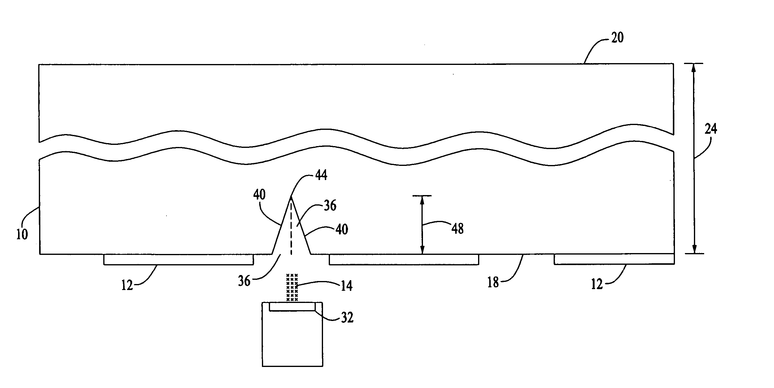
[0055] A scribe line was formed on a fired ceramic substrate material having a thickness of 0.913 mm using a Model No. V03 laser, manufactured by LightWave Electronics of Mountain View, Calif., emitting a 25 micron Gaussian beam and positioned in a Model No. 5200 laser system, manufactured by Electro Scientific Industries. The process was run at an effective rate of 0.5 mm / s (actual rate=25 mm / s / repetitions). The operational parameters used are listed in Table I.

TABLE IOperational Parameters.PRF3 kHzAvg. Power1.4 WMin. Power1.4 WMax. Power1.4 WWavelength355 nmStability*100%Energy / Pulse466.7 uJFluence95 J / cm2Speed25 mm / sBite Size8.33 micronsSpot Diameter25 micronsNo. of1 to 50Repetitions

*stability is a measure of pulse-to-pulse laser stability.

Repetitions are the number of passes the laser beam makes over a specific area.

[0056] Following formation of the scribe line, the ceramic material was broken along the line to form two sing...

example 2

Higher Power, Lower Repetition Rate Micromachining

[0057] A scribe line was formed on a fired ceramic substrate material having a thickness of 0.962 mm using a Model No. Q301 laser, manufactured by LightWave Electronics of Mountain View, Calif., emitting a 25 micron Gaussian beam and positioned in a Model No. 5200 laser system, manufactured by Electro Scientific Industries. The operational parameters used are listed in Table III.

TABLE IIIOperational ParametersPRF15 kHzAvg. Power7.27 WMin. Power7.25 WMax. Power7.29 WWavelength355 nmStability*99.3%Energy / Pulse484.7 uJFluence98.7 J / cm2

*Stability is a measure of pulse-to-pulse laser stability.

[0058] Three separate trials were performed at varying speeds and bite sizes as indicated in Tables IV, V, and VI.

TABLE IVTrial #1Speed25 mm / sBite Size1.667 micronsSpot Diameter25 micronsNo. of Repetitions1 to 2Effective Speed12.5 mm / s

[0059]

TABLE VTrial #2Speed  50 mm / sBite Size3.33 micronsSpot Diameter  25 micronsNo. of Repetitions  2Effectiv...

example 3

Higher Power, Lower Repetition Rate Micromachining

[0064] A scribe line was formed on a fired ceramic substrate material having a thickness of approximately 100 microns using a Model No. Q302 laser, manufactured by LightWave Electronics of Mountain View, Calif., emitting a 25 micron Gaussian beam and positioned in a Model No. 5200 laser system, manufactured by Electro Scientific Industries. The operational parameters used are listed in Table VIII.

TABLE VIIIOperational ParametersEffectiveWave-Avg.RepetitionEnergy / PulseMax.SpotlengthPowerRatePulseNo. ofWidthPowerDiameterFluence(nm)(W)(kHz)(μJ)Repetitions(ns)(kw)(μm)(J / cm2)3553.950781253.12301.10

[0065] The laser beam was moved at a programmed speed of 100 mm / s and an effective speed of 50 mm / s. The total depth of the scribe line was approximately 28 microns. Because the bite size was approximately 2 microns, there was significant overlap in each of the two repetitions. Following formation of the scribe line, the ceramic material was ...


PUM

PropertyMeasurementUnit
energyaaaaaaaaaa
energyaaaaaaaaaa
poweraaaaaaaaaa

Abstract

A method of forming a scribe line having a sharp snap line entails directing a UV laser beam along a ceramic or ceramic-like substrate such that a portion of the thickness of the substrate is removed. The UV laser beam forms a scribe line in the substrate without appreciable substrate melting so that a clearly defined snap line forms a region of high stress concentration extending into the thickness of the substrate. Consequently, multiple depthwise cracks propagate into the thickness of the substrate in the region of high stress concentration in response to a breakage force applied to either side of the scribe line to effect clean fracture of the substrate into separate circuit components. The formation of this region facilitates higher precision fracture of the substrate while maintaining the integrity of the interior structure of each component during and after application of the breakage force.

Description

RELATED APPLICATION [0001] This is a continuation-in-part of U.S. patent application Ser. No. 10 / 618,377, filed Jul. 11, 2003.TECHNICAL FIELD [0002] The present invention relates to a method of forming a scribe line in a passive electronic component substrate, and more particularly to a method of using an ultraviolet laser to ablate a passive electronic component substrate and thereby form a scribe line along which the substrate may be broken into multiple pieces. BACKGROUND OF THE INVENTION [0003] As is well known to those of skill in the art, passive and hybrid microelectronic circuit components (hereinafter circuit “components”), are fabricated in an array on a ceramic substrate. The ceramic substrate is cut, sometimes called diced, to singulate the circuit components from one another. [0004] For the past 30 years, the predominant method of singulating ceramic substrates involved using a pulsed CO2 laser dicing process in which a pulsed laser was aligned with and then directed al...

Claims


Application Information

Patent Timeline
Patent Type & Authority Applications(United States)
IPC IPC(8): B23K26/04B23K26/06B23K26/08B23K26/40B28D5/00H01L21/301H01L21/44H01L21/48H01L21/50H01S
CPCB23K26/063B23K26/367B23K26/408B23K2201/40B28D5/0011Y10S438/94H01L2924/0102H01L2924/01077H01L2924/09701H01L2924/01067H01L2924/01068H01L2224/16B23K26/40B23K26/0622B23K26/364B23K2101/40B23K2103/52H01L21/30
Inventor SWENSON, EDWARD J.SUN, YUNLONGSAMMI, MANOJ KUMARJOHNSON, JAY CHRISTOPHERGARCIA, DOUGANKLEKAR, RUPENDRA M.
Owner ELECTRO SCI IND INC
Why Eureka
Try Eureka