Apparatus and method for velocity estimation in synthetic aperture imaging

a technology of synthetic aperture and apparatus, applied in the field of apparatus and method for velocity estimation in synthetic aperture imaging, can solve the problems of data, not being clinically used, and higher hardware complexity, and still suffering from motion artifacts

Inactive Publication Date: 2005-02-24
B K MEDICAL
View PDF4 Cites 69 Cited by
  • Summary
  • Abstract
  • Description
  • Claims
  • Application Information

AI Technical Summary

Problems solved by technology

It has not been in clinical use because of the relatively higher complexity of the hardware and because of its inability to estimate blood velocities.
The data, however, still suffers from motion artifacts.
It is therefore not suitable for STAU.
This results in an increased bias and uncertainty of the estimates.
These images suffer from motion artifacts, which changes from frame to frame.
The success of the velocity estimation relies on the success of the motion compensation, which makes the whole approach unstable.

Method used


Image

  • Apparatus and method for velocity estimation in synthetic aperture imaging
  • Apparatus and method for velocity estimation in synthetic aperture imaging
  • Apparatus and method for velocity estimation in synthetic aperture imaging

Examples


Embodiment Construction

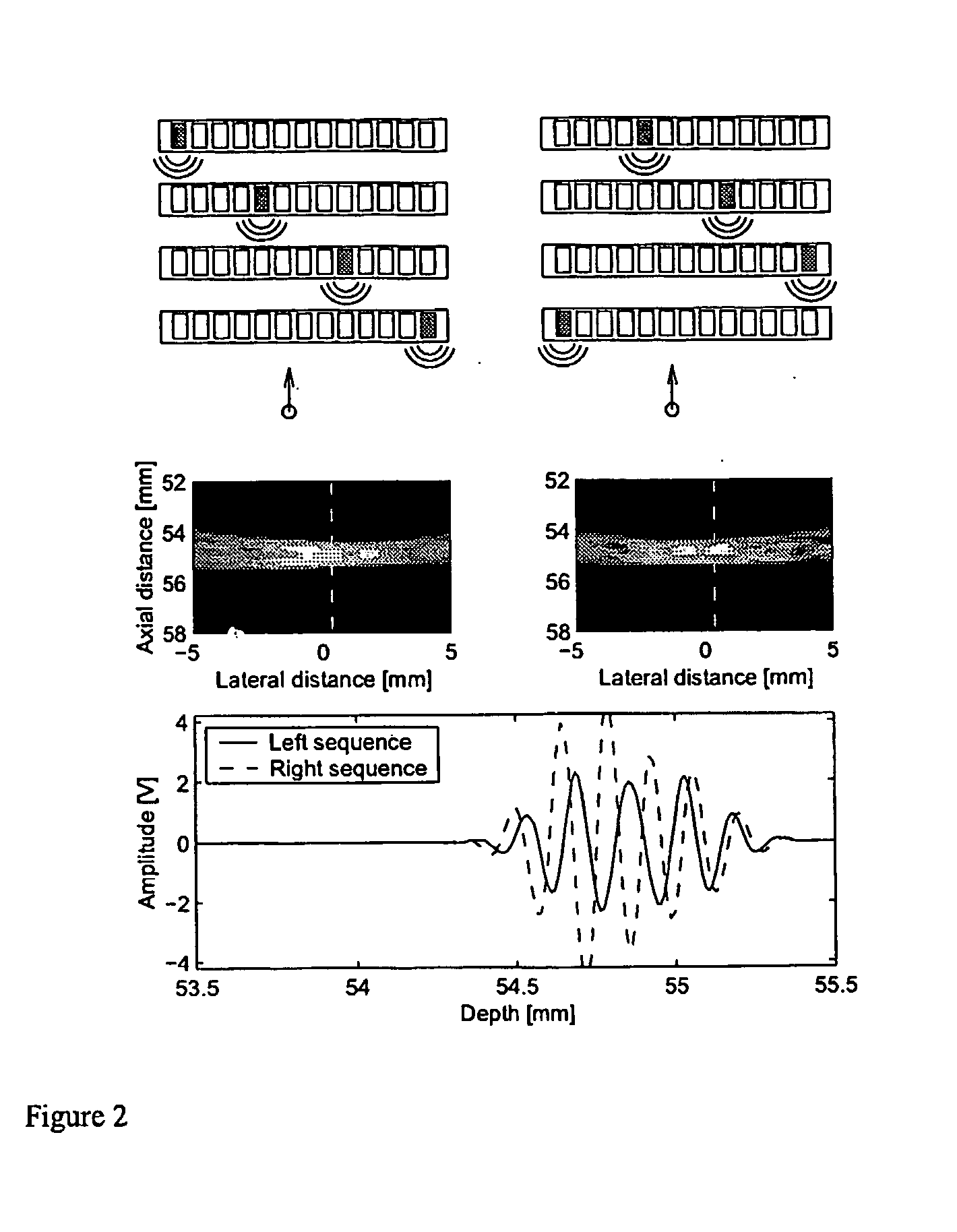
In FIG. 8 is shown an example of a preferred embodiment of an apparatus according to the invention. This embodiment of the invention has its application within diagnostic medical ultrasound. A typical example is visualization of the organs in the human body and determination of their blood flow.

In FIG. 8 the specific setup of the measuring apparatus itself is indicated schematically. It comprises a generator or pulser 1, an emit beam former 2 for selecting the transmission elements, a linear array ultrasound emitting transducer 3, a linear array ultrasound receiving transducer 5, a receive beam former 6 receiving signals from the receiving transducer 5, an update processor 7 for recursively updating the images, and an estimator processor 8 for estimating the velocity.

The pulser 1 generates a pulsed voltage signal with sinusoidal oscillations at a frequency of 3 MHz in each pulse, that is fed to the emit beam former 2. The emit beam former 2 splits up the signal from the pulser ...


PUM


Abstract

The invention relates to an apparatus for flow estimation using synthetic aperture imaging. The method uses a Synthetic Transmit Aperture, but unlike previous approaches a new frame is created after every pulse emission. In receive mode parallel beam forming is implemented. The beam formed RF data is added to the previously created RF lines obtained by the same transmit sequence. The apparatus comprises a pulser (1) to generate a pulsed voltage signal, that is fed to the emit beam former (2). The emit beam former (2) is connected to the emitting transducer array (3). The ultrasound is reflected by the object (4) and received by the elements of the transducer array (5). All of these signals are then combined in the beam processor (6) to focus all of the beams in the image in both transmit and receive mode and the simultaneously focused signals are used for updating the image in the processor (7). The estimation processor (8) to correlate the individual measurements to obtain the displacement between high-resolution images and thereby determine the velocity.

Description

FIELD OF THE INVENTION The invention relates to an apparatus and a method for determining the velocity of a remotely sensed object using wave energy such as sound, in particular ultrasound, or electromagnetic radiation. A synthetic aperture imaging techniques, where the received signals for a number of transmissions are grouped to form similar but spatially shifted images, is used to determine movement of the object, in particular blood flow. By using a number of pulse emissions, the inter-pulse movement can be estimated and the velocity found from the estimated movement and the time between pulses. The invention is based on the principle of using a synthetic aperture imaging over a number of emissions and then group the focused data to make the correlation between the focused and displaced images high in order to optimize the velocity estimation process. BACKGROUND OF THE INVENTION The use of synthetic transmit aperture ultrasound imaging (STAU) for tissue imaging has been consid...

Claims


Application Information

Patent Timeline
Patent Type & Authority Applications(United States)
IPC IPC(8): G01S15/58G01S15/89
CPCG01S7/52085G01S15/8915G01S15/8997G01S15/58A61B8/06
Inventor JENSEN, JORGEN ARENDT
Owner B K MEDICAL
Why Eureka
Try Eureka